


Dietrich’s Version 20
The most important updates at a glance
Version 20 of Dietrich’s software applications for construction and engineering is now available! Here we will discuss highlights focused on project involvement including consistent, complete planning processes from design to production as well as data exchange with other company divisions and departments.
Planning - Constructing - Dimensioning - Manufacturing
All processes are integrated in one model
We believe that unique requirements demand unique solutions. With each version of Dietrich’s, a detailed list of features and enhancements is provided so that you may judge for yourself what is important and valuable to you. While reading through this list you may find solutions to your unique requirements as well as hints to help ease your everyday routine.
We wish you great success with the new features and improvements in your update!
Visualization
NEW! Export Visualization Module
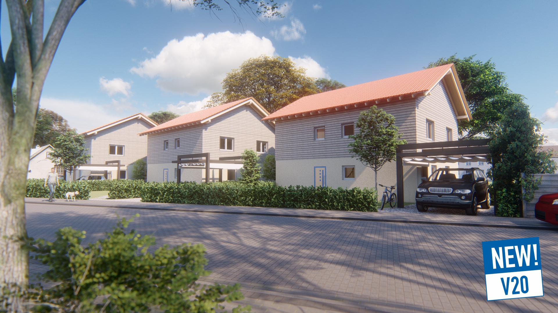
The new Export Visualization Module, in the powerful FBX format, allows you to use the rendering software of your choice to create professional visualizations of your project in its future environment. The robust rendering program from our cooperation partner Lumion is easy to use and offers extensive libraries including furnishings and plants in addition to various daylight-dependent exposures and shadings to help your clients see and understand their projects.
In Dietrich's, the building is excellently prepared for visualization:
- Building elements and components have textures adapted to individual surfaces in terms of type and alignment (e.g. end grain vs. longitudinal wood texture on a wooden component). This eliminates the need to assign textures to individual surfaces in the rendering system afterwards.
- These textures (materials) are grouped accordingly in Lumion, allowing you to adjust all textures of that type with a single selection. e.g. change the color of all wooden parts
- If there are any changes in the building, Lumion will export it to the same file again. In Lumion, the model can then be updated at the touch of a button and is automatically positioned accordingly.
NEW! 3D Web-Viewer module
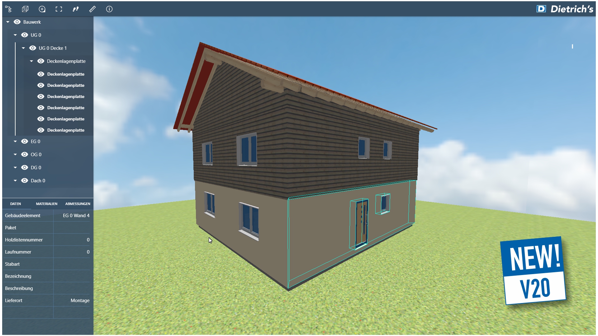
The new 3D Web-Viewer module was created to provide the client and other project participants with a comprehensive building model quickly and easily.
At the push of a button, a file is generated for the entire structure or the desired parts, which you simply send online in HTML format to your project partner. In addition to the building, the HTML file also contains the following operating functions for display in the 3D Web-Viewer:
- Visualization without installation, because it runs on all common browsers (Firefox, Chrome, Safari, Microsoft Edge, etc.)
- Intuitive, common navigation (turning, sliding). You can either move the building or the camera. To view the building from the exterior, moving the building is recommended. The camera is moved for inspection of the interior.
- Simple showing/hiding of the building parts via the building structure.
- Extensive display of important information on selected components: Material, designations, sequence numbers, properties, surfaces, lengths, heights, etc.
- Show and hide background and terrain.
- Full screen mode makes the best use of the available screen. Building structure and menu can also be hidden. Representation of the building has been optimized for tablets and mobile devices.
- Dimensions and distances can be checked with the measuring function.
We have provided a demo of the performance on 3dwv.dietrichs.com. Give it a try..
Construction
NEW! Processing point clouds
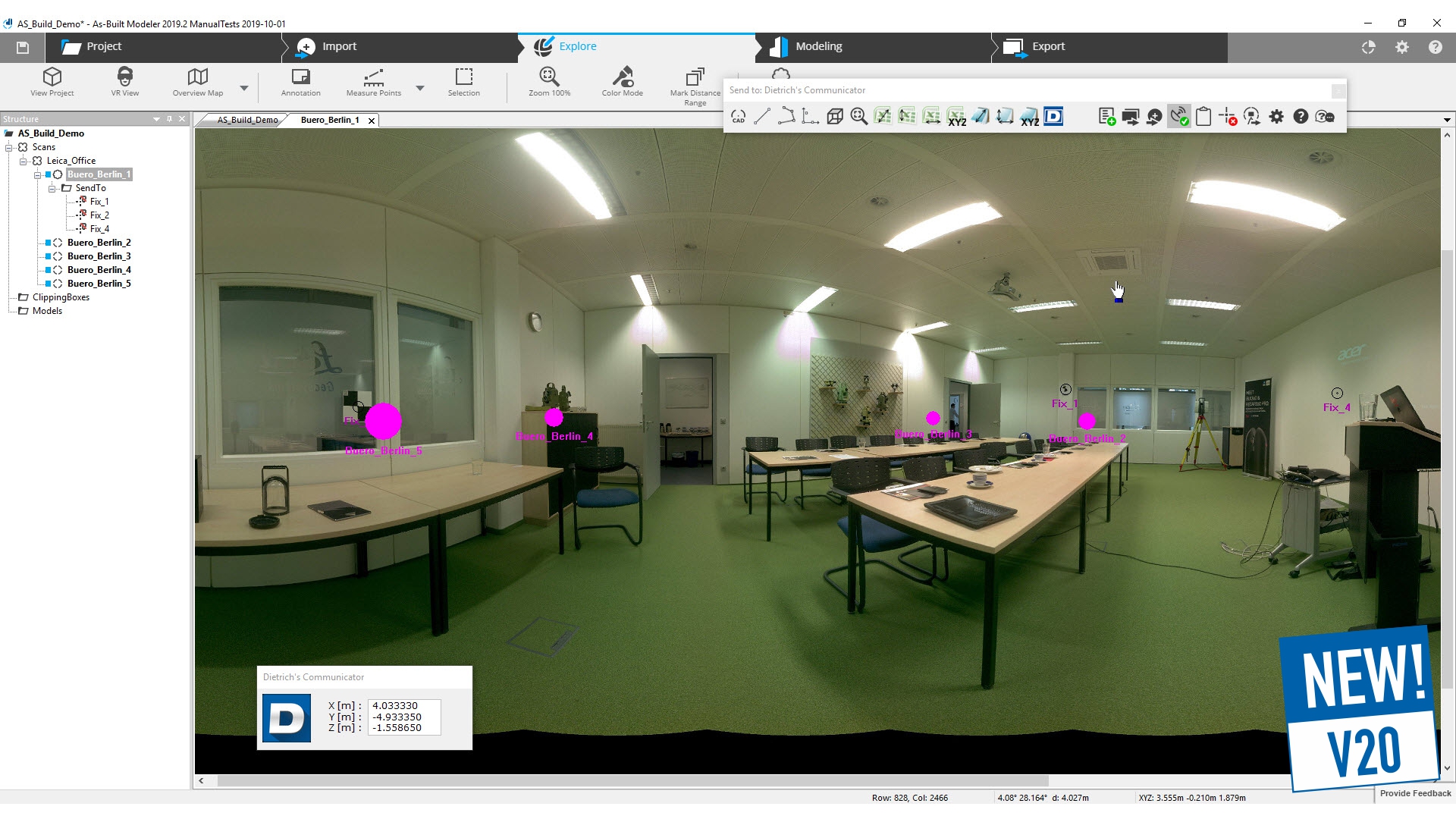
The use of laser scanners to record existing buildings is increasing. The new External input device As-Built™ Modeler makes these generated point clouds available in Dietrich’s for the evaluation of structures.
To do this, first load the point clouds in the external As-Built™ Modeler. A special display allows a very good impression of the room from which you select the points for transfer directly into Dietrich's construction. The procedure mimics the measuring at the construction site with a total station, such as the LEICA Builder.
In addition, orthophotos created with the As-Built™ Modeler are imported directly into Dietrich's construction. Special analysis functions of the Modeler generate lines that are also transferred to the construction via DXF and can be further processed there. So, you can easily edit the point cloud in the office, or call them up again, at any time, if you have forgotten to enter points. You can also transfer the construction from the building back to the As-Built™ Modeler and control it in the point cloud.
This connection can be used in all facets of the construction that require a point entry: Input of plan elements such as points and lines, creation of walls, positioning of windows or direct input of components. This is possible for 3D entries in DICAM as well as for 2D entries in floor plan and wall.
NEW!Transfer of drawings and images
Whether you’re using DXF, DWG, PDF, or other image formats (e.g. photos, print screens), the standardized import procedure makes information from these sources available in your plans and all areas of the building model: in ground plan, wall construction, and also in 3D work planes. The new Module, graphic interfaces - planning, makes it possible for you!
This is relevant as different graphic formats are often used for the same purpose. For example, site plan files can range from scanned paper plans to DXF/DWG. With the new imports, you can take over the information digitally for use in Dietrich’s. Characteristics include:
- A PDF can be either a pure image (raster) or contain real CAD elements such as lines (vector). You can choose to underlay as an image in the background, or convert CAD elements to points and linework, etc.
- Choose the section you need and eliminate unnecessary information.
- Directly choose precise alignment and scale when importing.
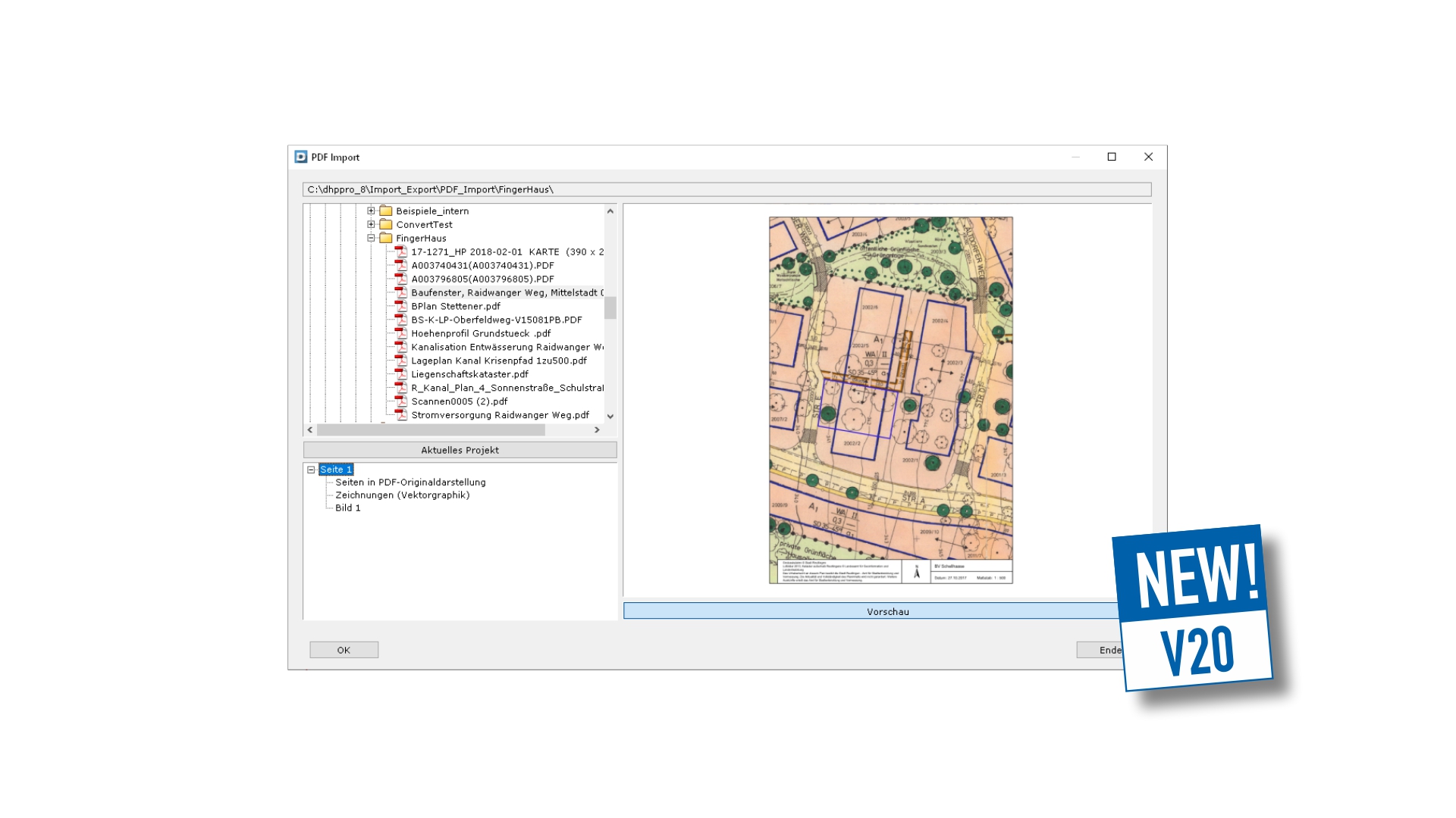
Plate input
We have further improved element design for you. In the future, element edges will be automatically detected when inputting plates. You can then choose whether you want to separate them at the element joint. Plates are then separated with set offsets at element boundaries. Accordingly, they are retained even if the elements are recalculated.
Automatic construction down to the last detail, and according to your settings, means efficiency. New options for plates on hip and valley lines are another example. Plate ends adjust automatically depending on your settings at the reference (e.g. hip line or opposite roof surface) and consider the defined offset.
BIM - IFC - Colaboration
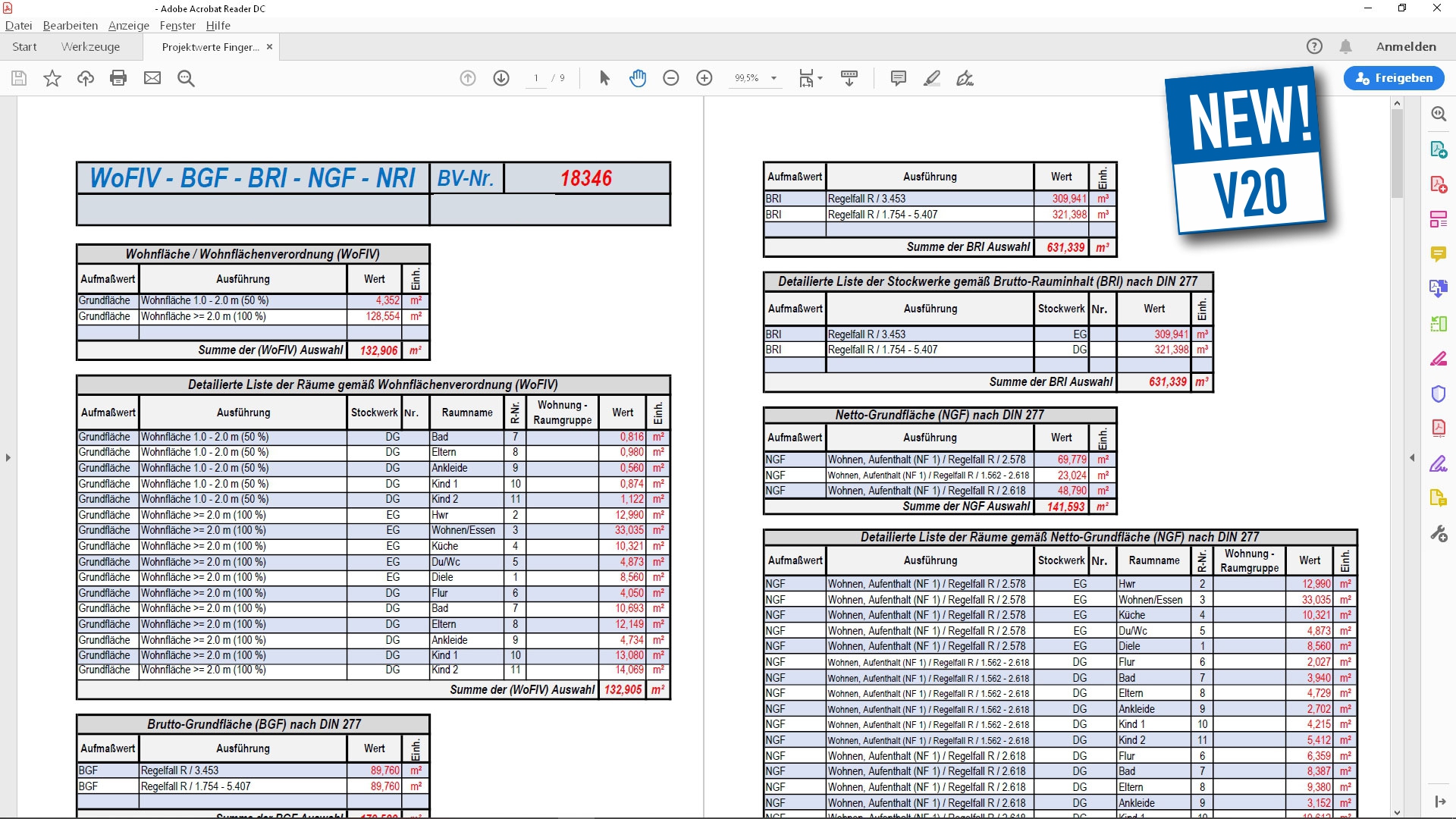
NEW! Project Data-Excel Transfer
Excel is used as a universal tool for revising and formatting information. With the new Module, Project data-transfer to Excel, you can use it even more efficiently.
This allows you to conveniently write construction data from the Dietrich's project to specific areas of Excel files where they can be further edited and formatted. Project information (e.g. address data, delivery date), values from dimension takeoffs (e.g. living space, room dimensions, wall, ceiling and roof areas) and material values (such as lengths, surfaces, volumes) are transferred. Measurement values can also be structured and summarized. Project-data Excel transfer is used for many purposes: Building applications, preparation of values for ERP systems, lists for suppliers and cooperation partners, as well as lists for workshops and building sites.
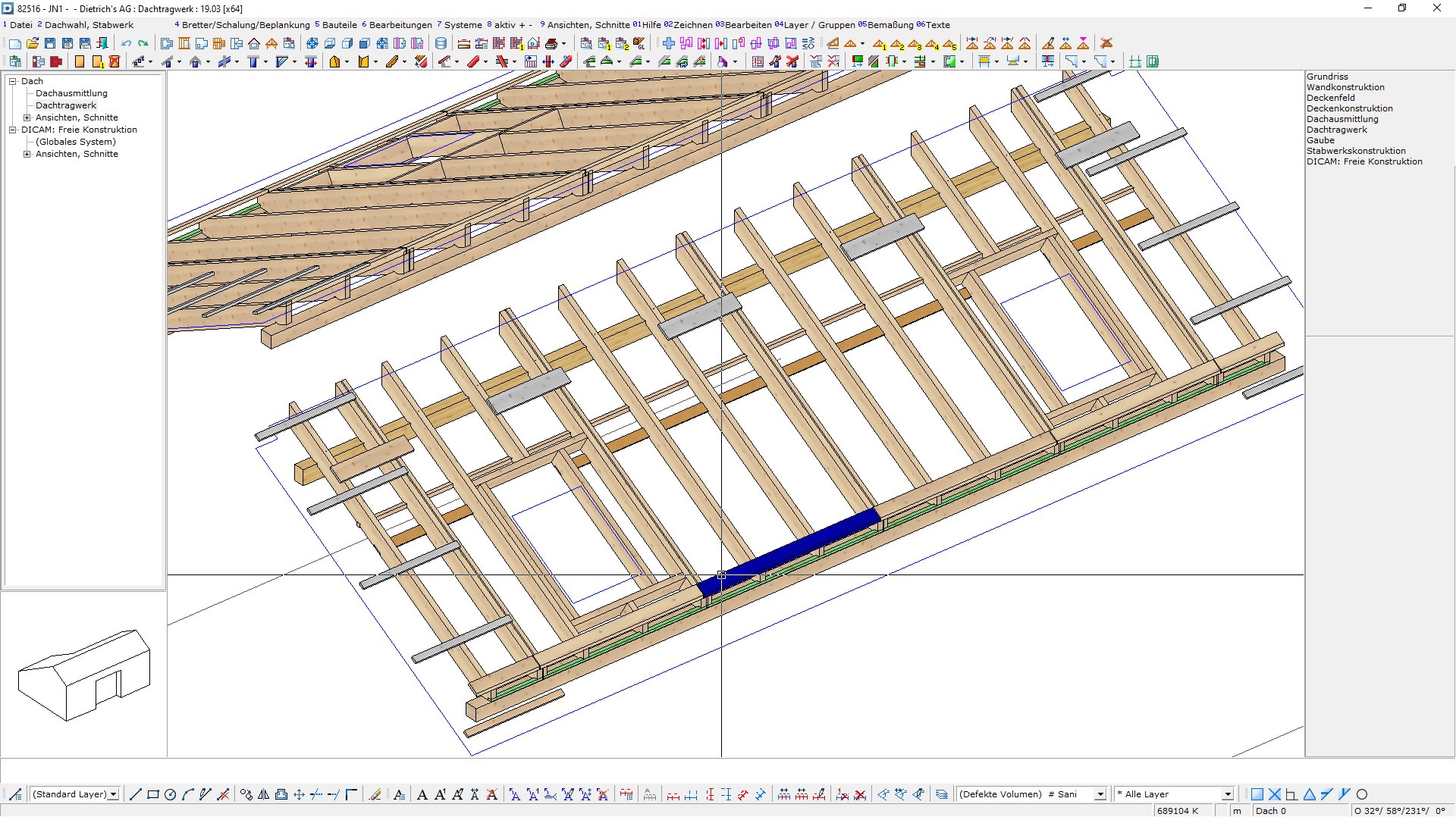
IFC-Import
Optimierung Import von Dächern: Die Formulierung von Dächern im IFC ist ungeeignet für ein Dach im Sinne der Dachausmittlung; es gibt z.B. keine Hauskontur. Daher erfolgt beim Import von Dächern aus IFC eine umfangreiche Formenanalyse, um die wirklichen Dachflächen zu finden und eine Hauskontur zu Ermitteln. Somit erhält man ein ausmittelbares Dach für eine erforderliche Nachbearbeitung. Das hilft bei der Anpassung der Dachüberstände aufgrund der Ziegelteilung oder bei der Anpassung der Dachneigung, um Verfallsgrate zu vermeiden.
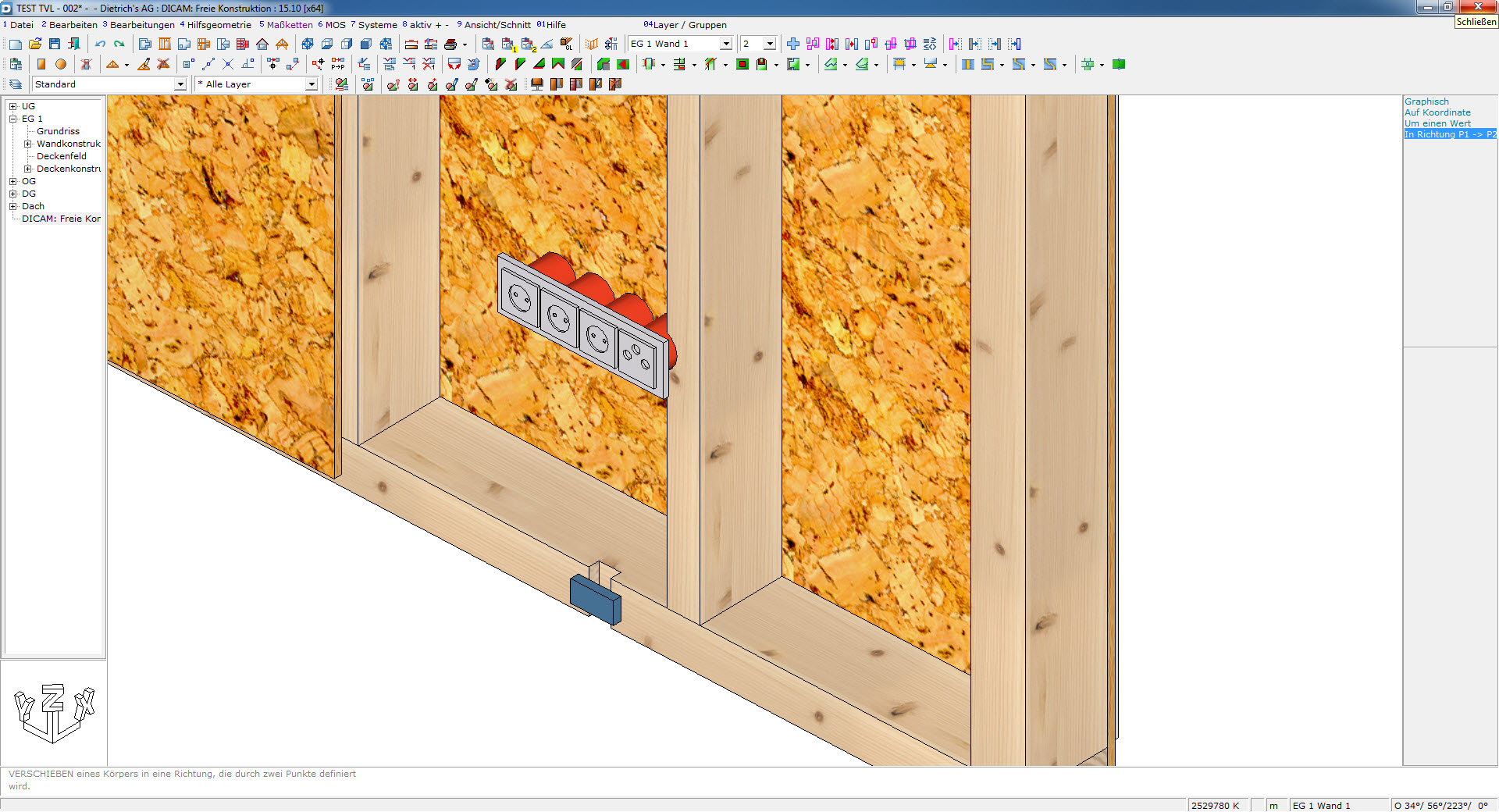
Bauteile zur Erzeugung von Nischen: Verschiedene Einbauten in Wände und Decken lösen in der Planungssoftware noch keine Nische in der Wand oder Decke aus, z.B. Elektrodosen. Das Bauteil selber ist aber bereits vorhanden. Beim Import werden diese Bauteile einstellbar direkt zur Erzeugung von Nischen verwendet. Die so erzeugten Nischen werden dann mit den komfortablen Funktionen der Kombielemente und im HRB-System weiterverarbeitet.
Organization
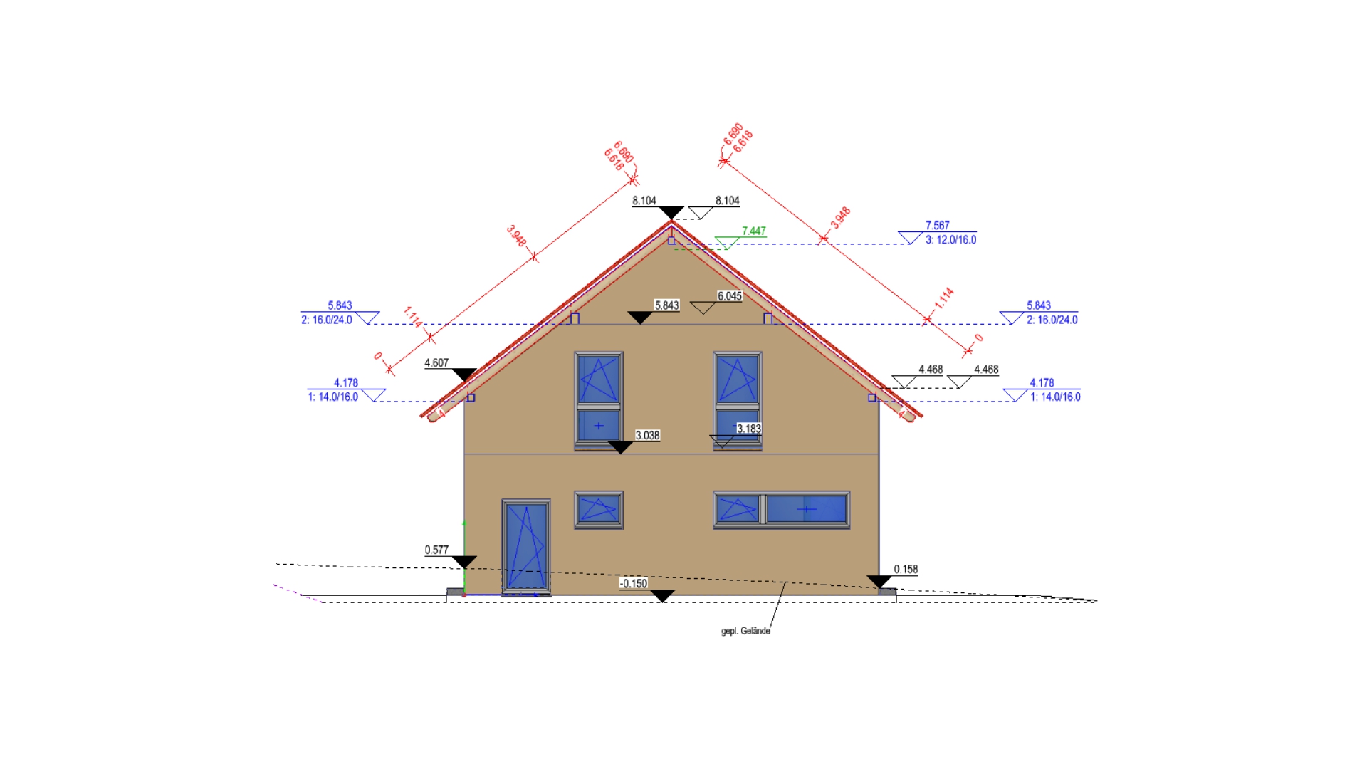
Views, building sections, section plan
In the initial planning phases, you will work mainly in views and sections. Now you can select them directly in building navigation. The selection is convenient and fast. For example, the change from the floor plan is done with one click. The creation of views and building sections also benefits from new capabilities:
- Positions of sections in the building can be moved; the dynamic section plan is recalculated for the new position.
- In the section line, there can now be any number of offsets; relevant areas of the building can be mapped with fewer sections.
- Section edges of cut building segments are now transferred as full lines with wider line widths in section plans.
- In the building, you can enter a terrain contour in the building section; when creating the section plan, all elements below the terrain contour are automatically displayed with dashes. Complex contours at cellar access points or windows can thus be easily displayed without having to model the 3D terrain.
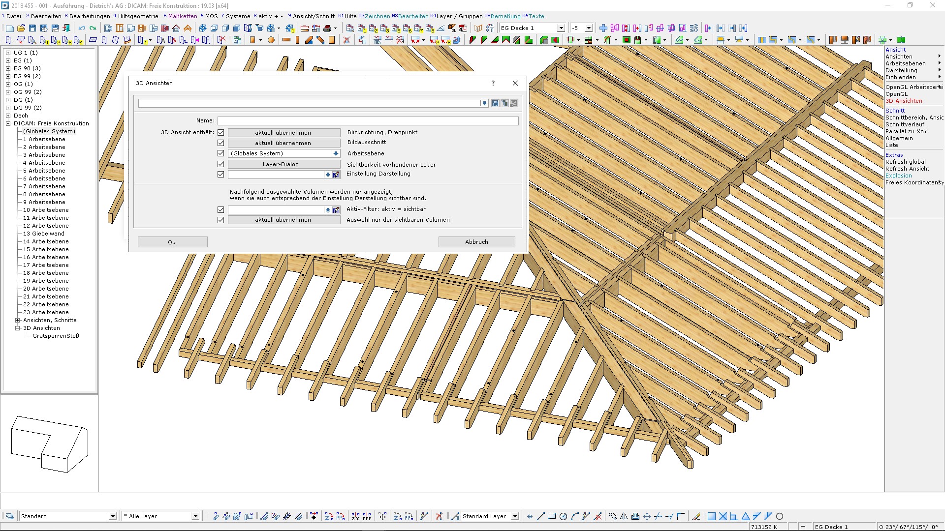
3D Views
Different areas of a building have varying requirements for both input and representation. In many instances, fast switching takes place between model areas. For special designs, details, and, especially, 3D designs, 3D views now provide a powerful basis for input and output.
In a 3D view, the view direction, display options, activated layers, active work plane, etc. are saved. These settings can be called up again at the push of a button and the required components are displayed in the corresponding perspective. For optimal access, 3D views are listed in the building navigation. 3D views are also the basis for the new dynamic view plans.
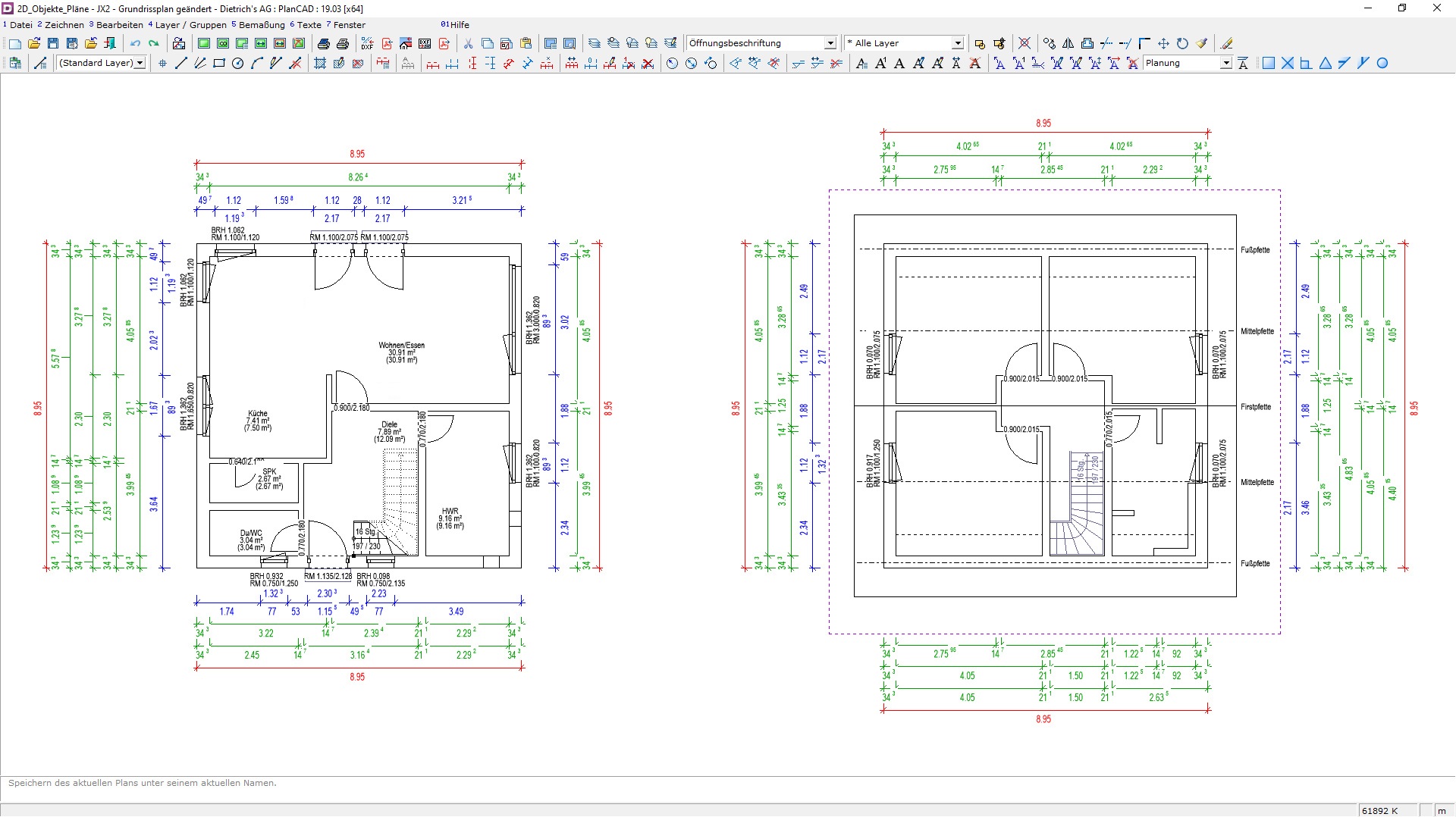
Floor plans
Floor plans are among the most frequently used and important documents used for input and planning. The following (a few of many new options) allow increased automation and are also updateable in case of subsequent changes to dynamic plans:
- Optimized dimensioning of exterior and interior walls on the corresponding side of the building
- Ability to specify a boundary contour for positioning dimension chains; the dimension chains are thus automatically kept outside this range
- Displaying and labeling of plates above the floor plan
- New options to display stairs from current and lower floors
DC-Calcs - Timber Constructioin-Engineering
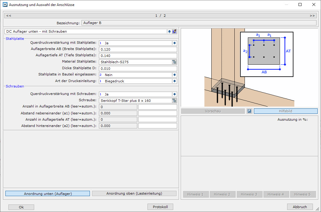
Lateral pressure reinforcement
It is not uncommon for bearing pressure to be decisive for statics when supporting wooden components. When calculating continuous beams, you can now determine steel plates for transverse pressure reinforcements on supports and load introductions to reinforce these areas. If one steel plate is insufficient, additional full-thread screws can be used, which transfer the existing forces evenly into the interior of the wood.
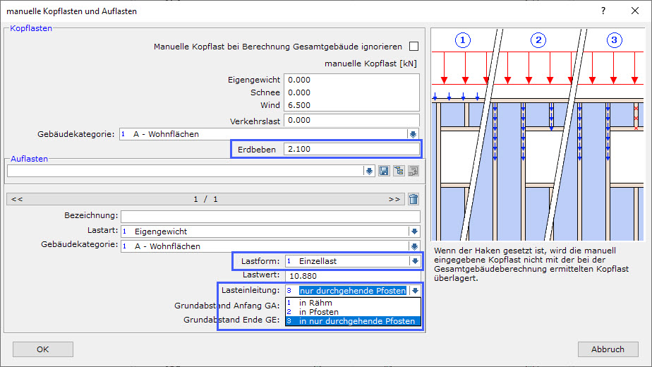
D-Calcs: Lateral bracing timber frame construction
The mathematical proof of building stiffening according to the method of professors Colling/Kessel is innovative and accurate. According to this method, executed wall construction is verified. In order to document all results conveniently and in detail with D-Calcs, the calculations and the documentation options have been further refined.
- For the first time it is now possible to enter individual loads with various options directly on the wall.
- With the new option of entering earthquake equivalent loads on the individual walls, D-Calcs supports you in seismic assessment.
- The anchoring plan allows you to automatically display the necessary anchors in your floor plan.
With version 20 of Dietrich's, extensive improvements advance the digital tools at your disposal:
- FC Import: Optimization for Importing Roofs
- IFC import: use of certain components to automatically create niches
- Living spaces and Room determination: The convenient, automatic determination of these values has been further expanded.
- Stairwell module: Staircase landings and semi-saddled staircases have been added.
- IFC export: The new export of Rooms in IFC extends the contents for coordination with clients and planning partners, e.g. transfer to software for building physics, EnEV, heat load determination
- D-Wall 3D: new AutoWall function now included in scope of delivery
- HRB system: again, powerful extensions of rules and details to reduce follow up work after preparation.
Talk to your account manager or contact experts@dietrichs.com
We are here for you!


