
Fire Tower Engineered Timber
Joe Miller was already a Dietrich’s software user when he joined FIRE TOWER ENGINEERED TIMBER.
Here’s how Joe describes engineering with Dietrich’s software.
ENGINEERING DATA:
“In Dietrich’s, generating a model for 2D planar analysis is a snap. All you do is highlight a member on the plane you want to be included, and then use a command that automatically generates engineering centerlines. It puts all of the member centerlines (regardless of member thicknesses or slight offsets) on a single plane and breaks centerlines at intersections of the members. These centerlines are then exported as a DXF, which can just be imported directly into the FE program. It is really quite slick. No more recreating geometry in your FE program.”
FINITE ELEMENT (FE) MODELING:
“Dietrich’s really stands out in this category, and was one of the main selling points for someone like me. Most softwares allow you to export the member axes, but, with timber frames that have various cross sectional widths and run continuous past some members but not others, a lot of clean up is required. With Dietrichs and their ability to generate centerlines on a single plane, this allows me to go directly to Visual Analysis which handles timber design quite well.”
3D FE MODEL:
“In Dietrich’s, you go through and create sets of engineering centerlines for each bent, wall line, etc and then export them all together as a single 3D DXF. You then can adjust them in a 3D DXF editing software if need be, although I am regularly able to import it directly into my FE program. If you have non-planar (e.g. “compound”) elements, you can also export their centerlines as well.”
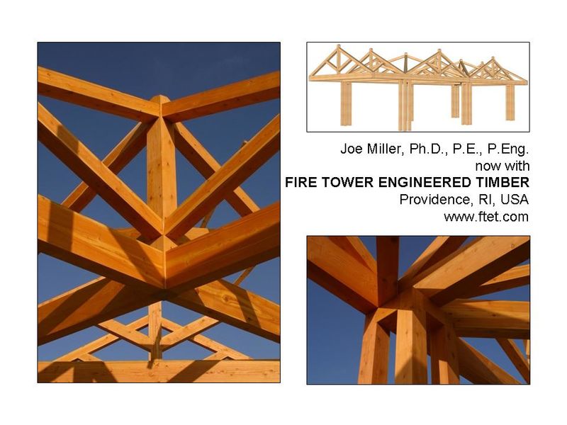
Joe Miller, Ph.D., P.E., P.Eng.
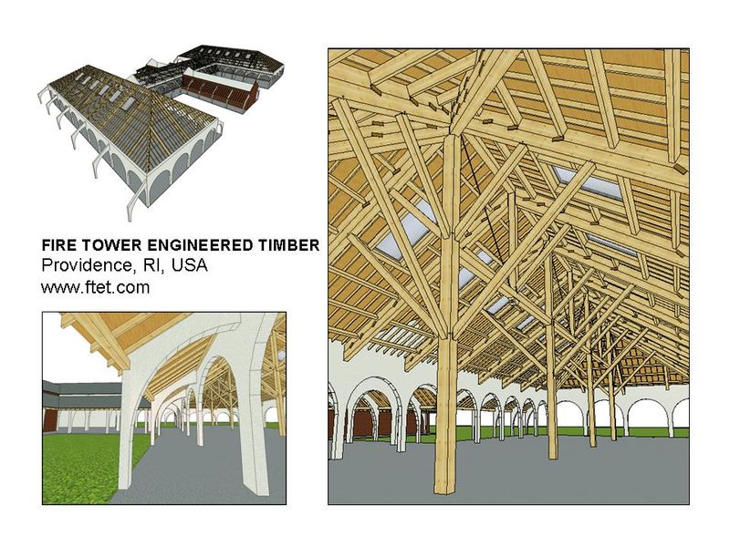
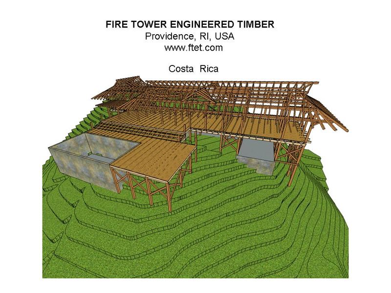
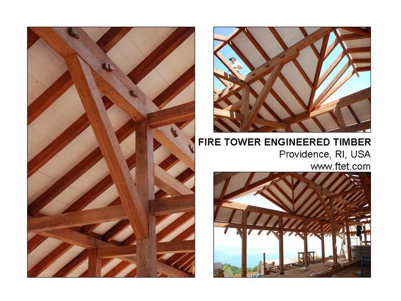
FIRE TOWER ENGINEERED TIMBER