Dietrich's Version 22
The most important innovations at first sight

Timber construction has become more modern than ever! With the new Version 22 we have taken this trend and its further increasing requirements into account. Dietrich's technologies provide you with the optimal digital tools for a continuous CAD/CAM value-added process in the timber construction.
Planning – Constructing – Dimensioning – Manufacturing.
What can you expect?
On one hand, these are extensive update services that make your software maintenance and support contract even more valuable. With functions, such as basic views, the cloud connection for the 3D web viewer or the completely revised Do/Undo procedure, your work simply becomes better, faster and more efficient.
On the other hand, there are the new modules point cloud and assembly sequence. Both technologies are genuine innovations without which you will soon not be able to imagine your digital work preparation anymore. Like this user:
Planning / Construction
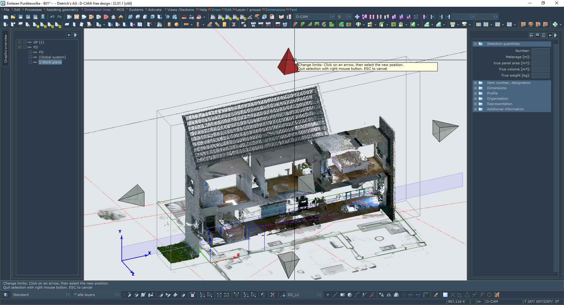
New Module: Point Cloud in the System
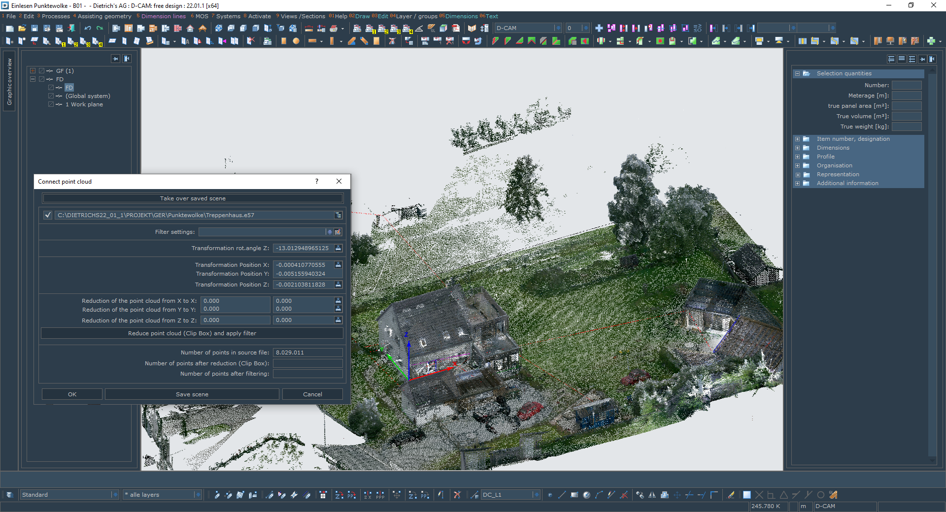
When planning in the existing structures, incorporate the existing structures into your planning!
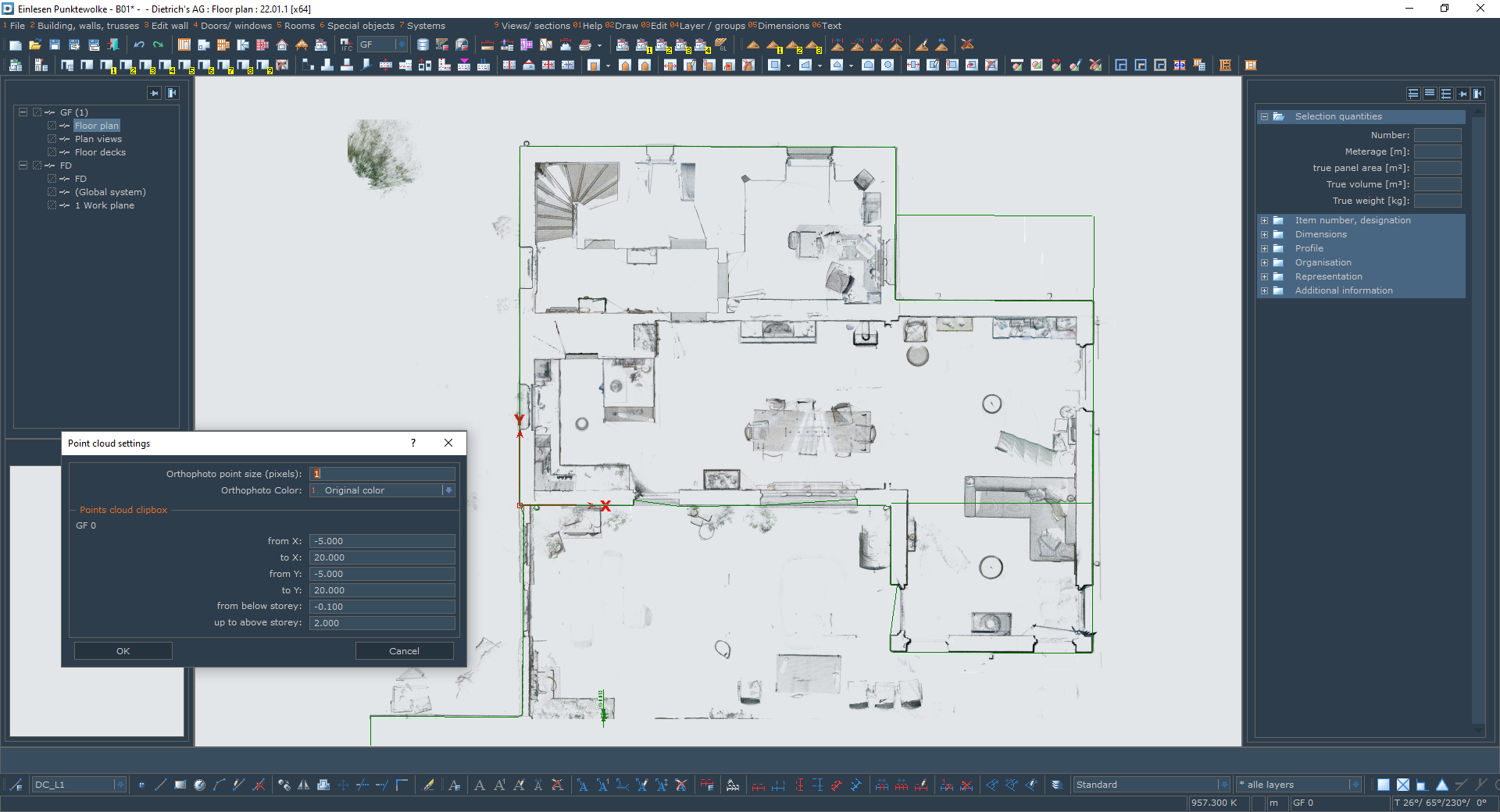
For the enlargement or renovation of existing buildings, measure the existing building structures with modern measurement technology, in particular laser scanning. Millions of measurement points are created, the so-called point cloud. With the new module, you can now import the point cloud directly into the Dietrich's Construction Program and work with it. Planning and construction are directly oriented to the real state of the object.
To make this possible, the several gigabyte large point cloud can be reduced so that you can work with it reasonably on your CAD computer. For this purpose, the system offers new filter techniques, convenient alignment and the clipping of display areas to a certain section (so-called clip box). So prepared parts of the point cloud can be saved as a scene and can anytime be quickly loaded. Practically any size of point clouds can be split into these scenes smoothly and be conveniently used.
For direct work with the point cloud these following functions are available:
- The points can be selected as 3D points. That way they are used directly as reference for inputs and positioning or they are used to determine distances.
- In working planes, point clouds have their own clip box, with which the point cloud can be further reduced to the situation required for your specific application. This increases overview and avoids selecting the wrong points.
- Orthophotographs are generated in the working planes according to their clip box. These enable convenient input of drawing elements, such as lines, circles, but also dimensions. In particular, the input of lines supports the point cloud to approximate for CAD.
- For floors, as well, an adjustable area from the point cloud is provided as orthophotograph. That way you have the optimal basis for example for the input of walls with window and door openings.
The point cloud module can process data in E57 format, as provided by all manufacturers of laser scanners. That way you are free to choose your own scanner or you can use point clouds from partners or service providers who provide you with scans.
Basic Views
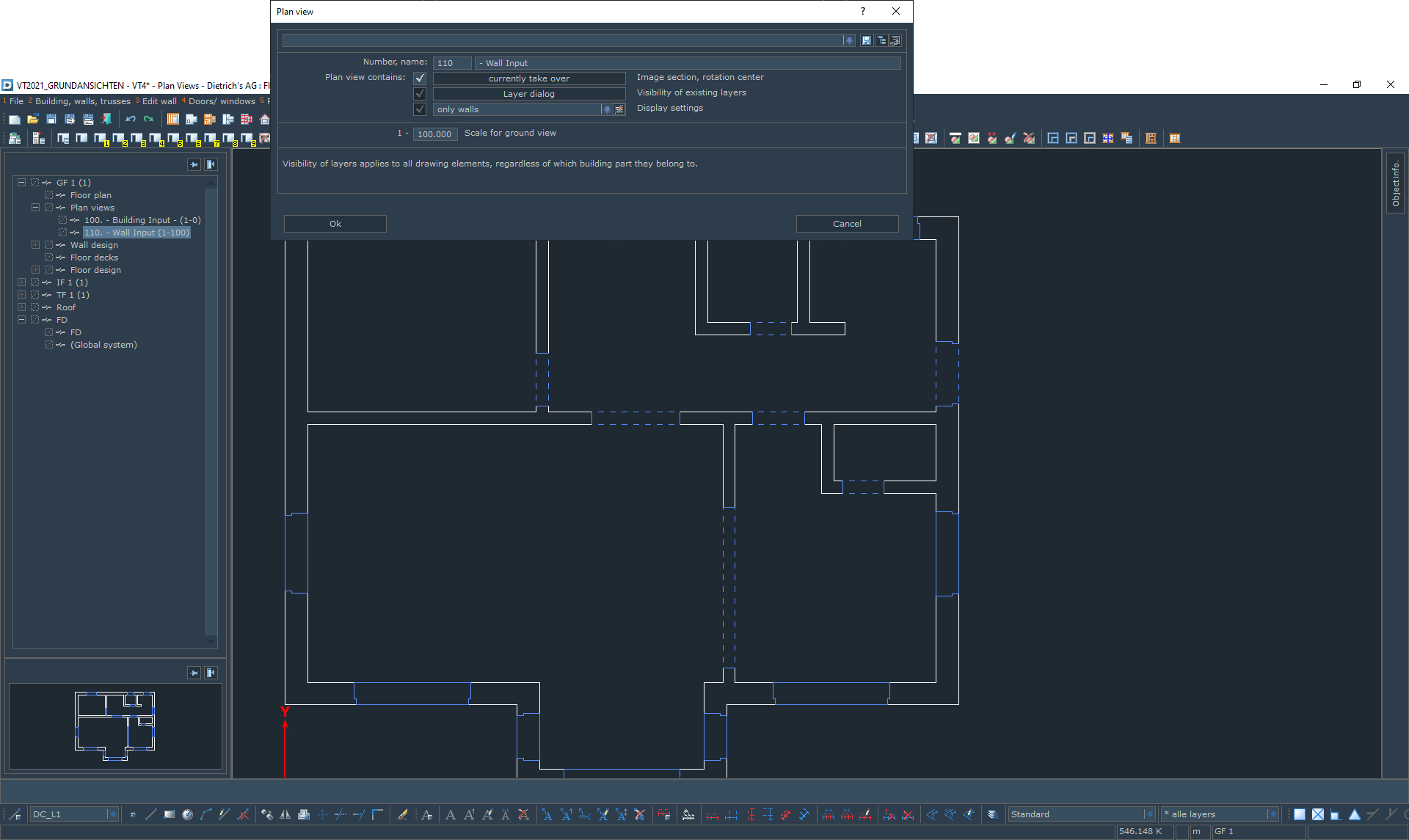
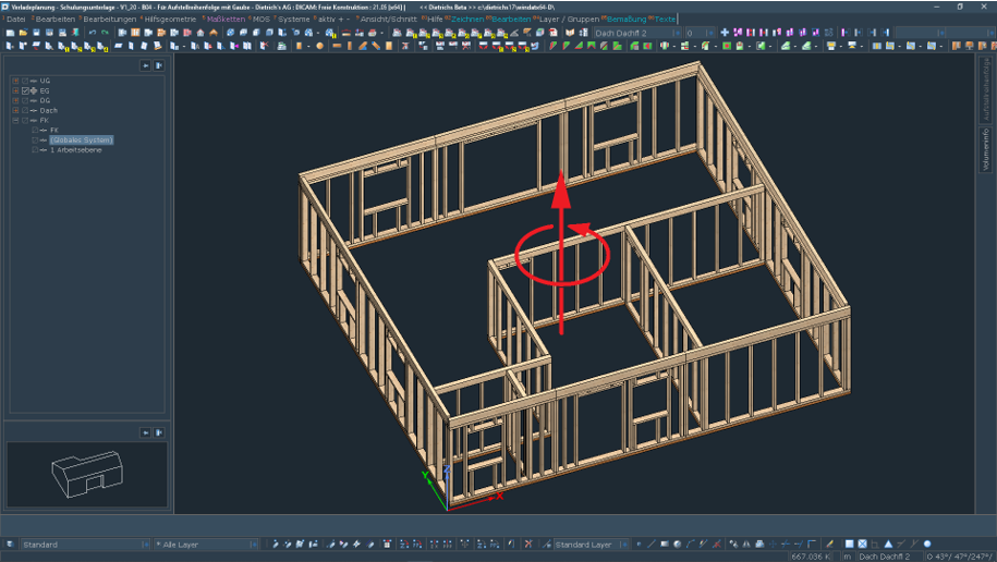
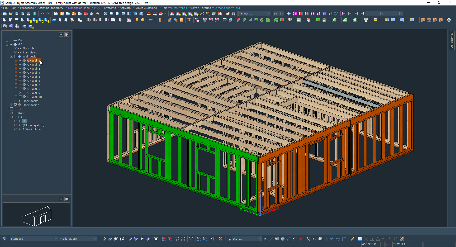
The floor plan is the basis of many tasks in timber construction, starting with the design planning all the way to the construction.
Depending on the task, the requirement is on the illustration and displayed information. With the new basic views, we enable you to create adapted views on the floor plan.
For each floor, any number of basic views can be created. A basic view has a number for identification and a name for explanation. It‘s settings contain the screen display, automatic dimensions and labels and the visibility of layers. The basic view can also be defined to a specific section.
If a basic view is now selected, these settings are applied and the appropriate view for the task is displayed on the screen. Then with one click you are in the next view for the next task.
Plan elements, such as lines, circles, texts and dimensions that are entered in the basic view belong to it. So also, their display can be controlled. It is not necessary to create different layer variants. Since these plan elements can also be displayed in other basic views, they need to be entered only once.
The basic views are furthermore a look at the floor plan, i.e. the walls, windows and doors. This floor plan can be edited in all basic views, i.e. walls can be entered, moved, etc. The adjustments are conducted in the most suitable context for this purpose. Vice versa, they are instantly available in all basic views.
Typical are the basic views for preparing the required plans. In that way you can, for example, prepare a story entirely for the application plan, i.e. including the texts, dimensions and other drawing additions. For the actual plan, only the baasic view is filed. There is virtually no more post-editing in the plan itself. The great advantage of the basic view in the building is that it can be edited and checked immediately after modifications in the building. With the new function, you no longer have to switch to the different plans.
The settings of the basic views can also be transferred to other buildings using the usual functions. It is also possible to save an otherwise empty building with all basic views as a template. To plan a new building, start with one of your templates, all the basic views are already created and the building is all optimally prepared
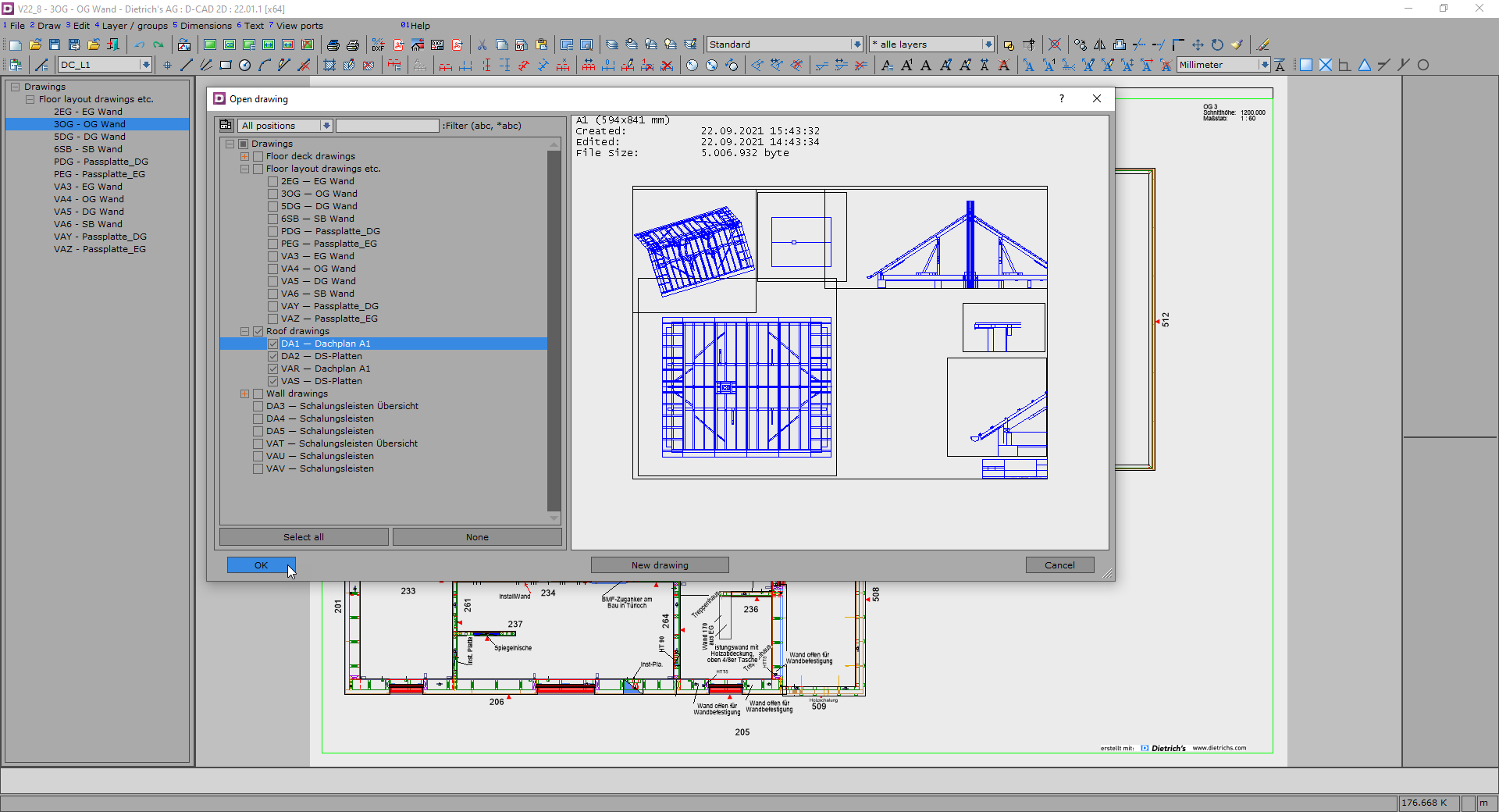
Plan Management, Dialogs, optional Plan Numbers
There are often hundreds of plans created in complex projects. The new dialogs for plan management and the extended plan numbers support the work with a large number of plans. The dialogs make structures transparent and allow you to navigate in a safe way.
The tree-structure-like display of categories and the optional display of the corresponding building position create a convenient overview. The dynamic filter function instantly reduces its display to the desired plans. And when you need the graphical preview for a precise identification, you can use the whole screen by means of the now dynamic dialog.
Plan numbers can now be of any length. This way "speaking" numbers can be used. The term "wall plan" in the name says already quite a lot about the content. The plans can be clearly recognizably structured, for example all wall plans of the first floor can be started with “WP_GF_”. If PDF files are created from the plans for distribution or document management, then the plan number can now reasonably be used as filename. There is always a comprehensible reference to the plan.
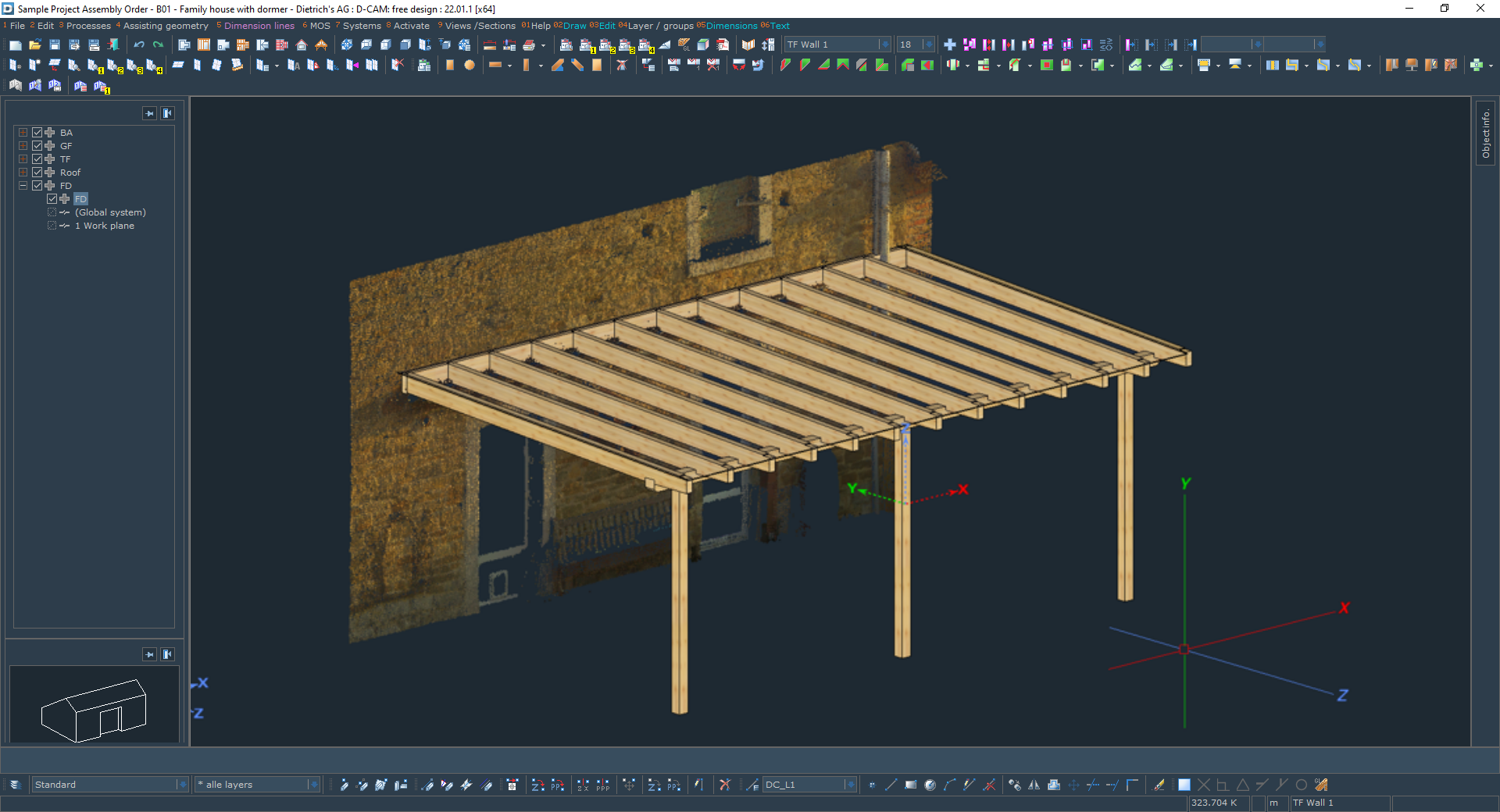
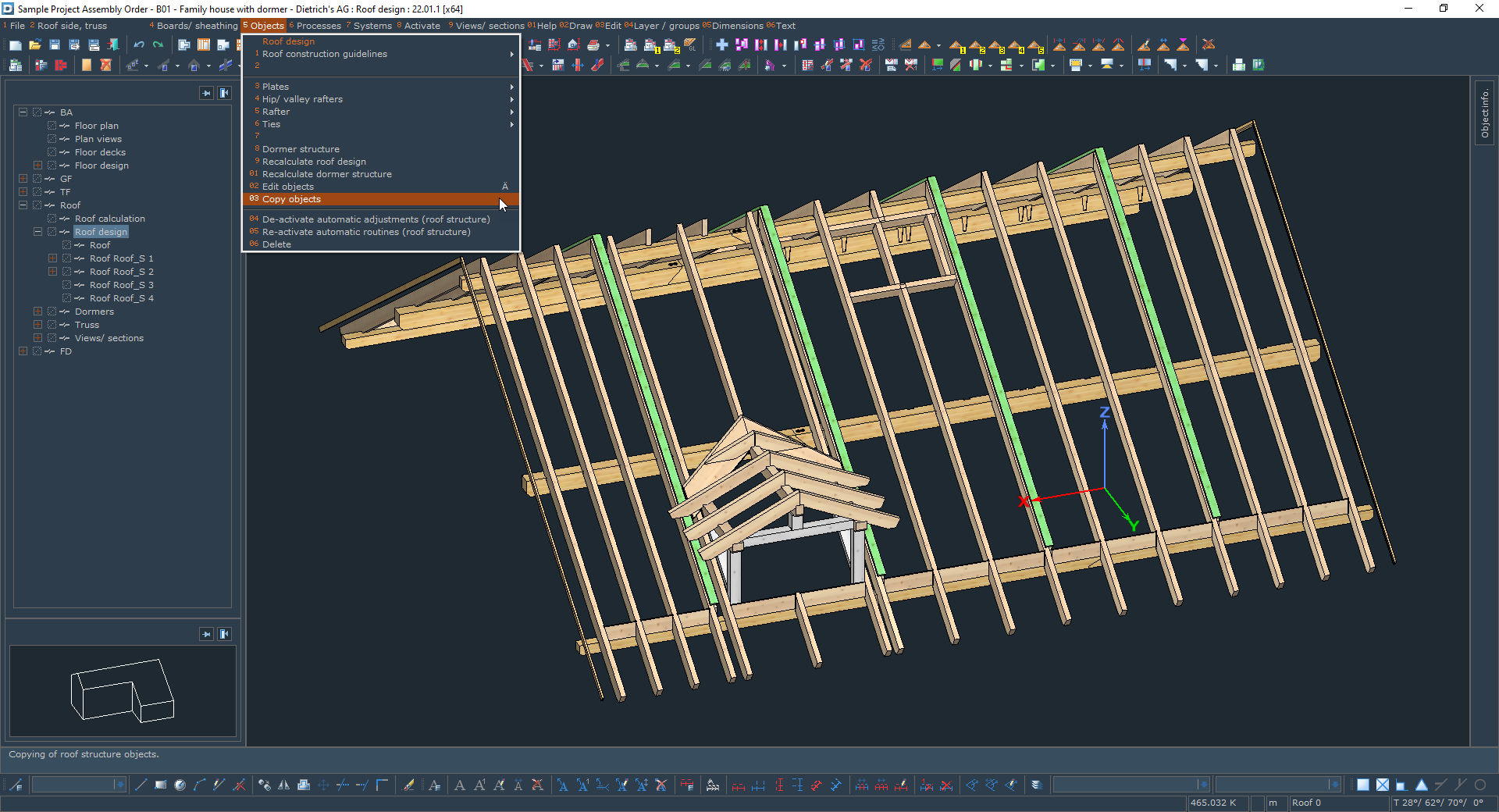
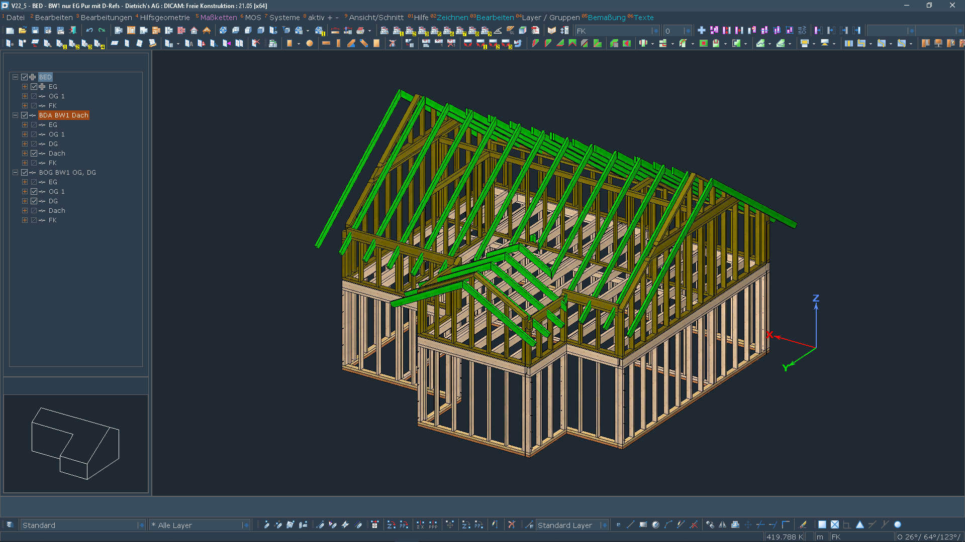
Construction: Copying Components in the Roof Structure
In the Dietrich's Construction Program, the individual components of the roof structure are entered quickly and conveniently using parametric inputs. When changes are made to the roof geometry, they will adapt accordingly. If the same or similar individual components are required on other roof surfaces or are later supplemented, the new copy function for the roof structure provides the optimum work method. You do not have to select and check the corresponding settings again, but can simply copy existing individual components. According to their parameters, the copies will, of course, be adapted to the new situation, and so, even in the new situation, a rafter will create the correct birdsmouths with the purlins. Manually added machining operations of the original components are also adopted. A typical example for this is compound head machining.
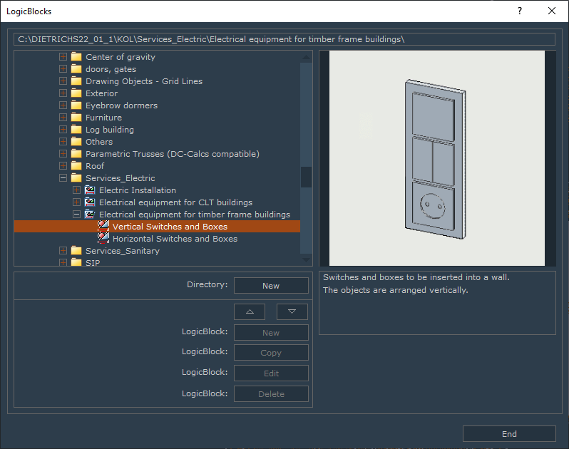
Logic Blocks: Re-reading and Calculation
Often a long time passes from the beginning of planning until the start of production. During this time, there are still many changes in the construction. The used materials or fittings change or more suitable processes were found for the machine. For efficient working, logic blocks are often used in the design. These logic blocks are adapted to the new requirements. In already current and prepared projects these revised logic blocks now have to be applied. With the new function, the logic blocks are reread and recalculated via push of a button. The preserved positionings and set values are being maintained. With minimum effort, you can implement your current production standards into already planned projects.
“Great compliments to the module point cloud, it facilitates our lives so much once again. The solution is absolutely awesome! For working in existing structures and working with the point cloud, I consider the history of 3D laser scanning as having the same potential as the former move from the drawing table to CAD!“
Manufacturing
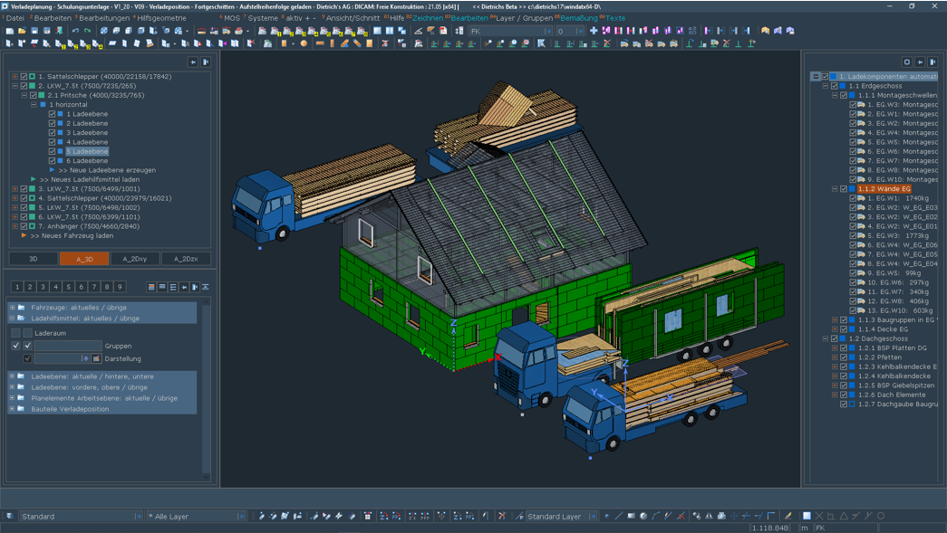
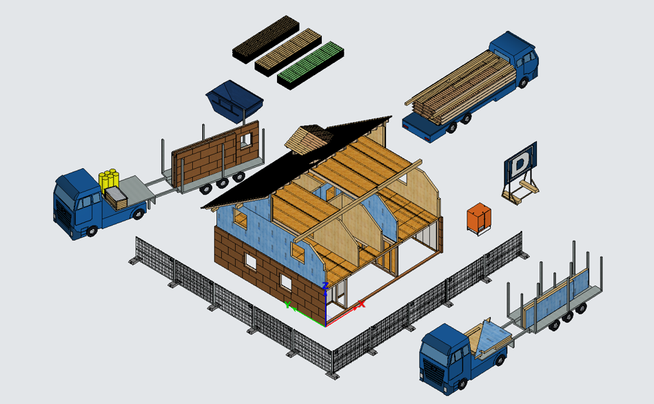
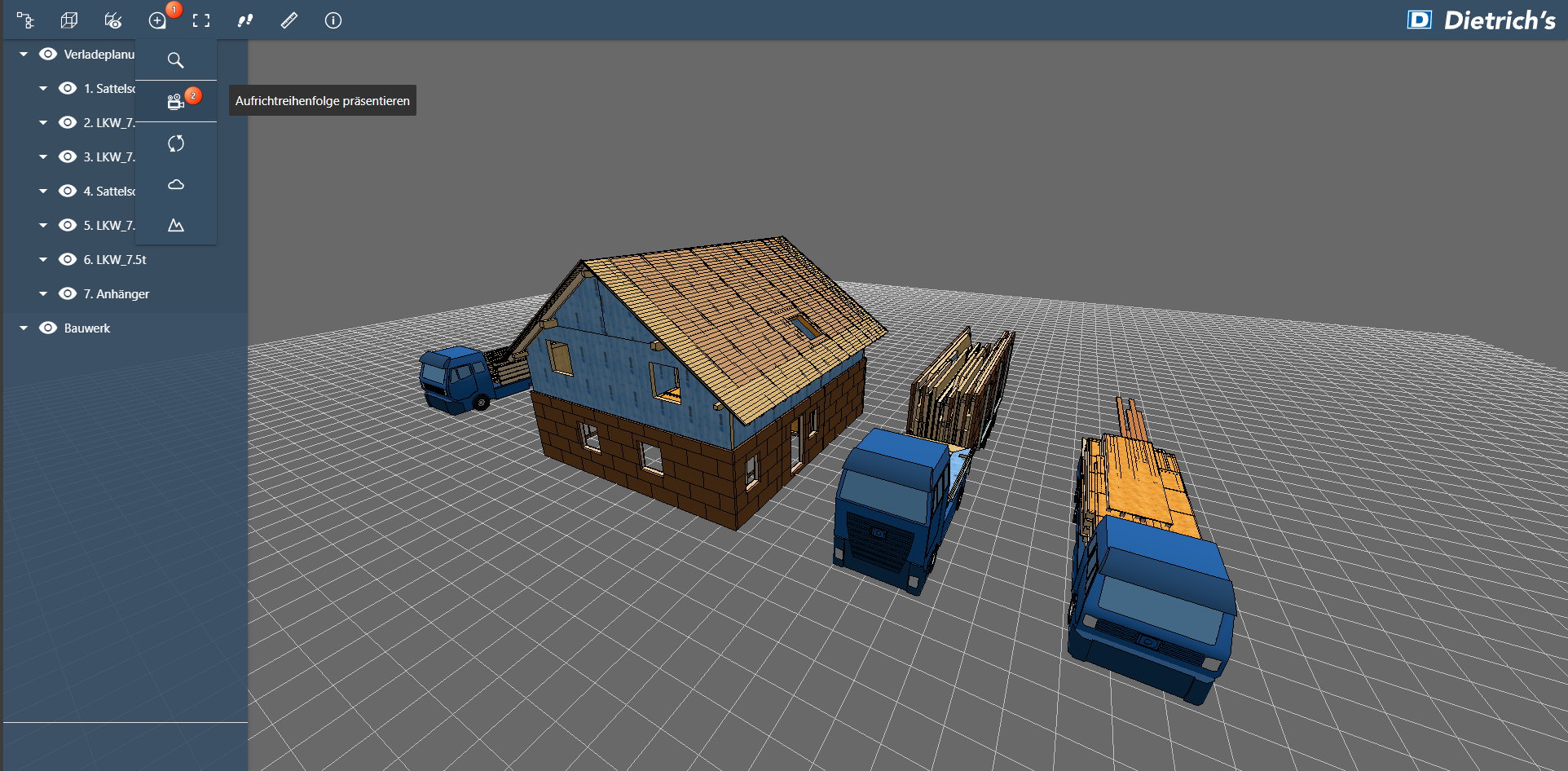
New Module: Assembly Sequence in Building and Load Planning
After manufacturing, logistics and erection are decisive phases in the project on the way to the finished building. Optimal pre-planning of these phases ensures the economic success of the project. With V21, we already introduced load planning to make logistics plannable.
With the assembly sequence module, the ideal tool for planning and preparing the assembly sequence is now available, as well. The assembly sequence can be used as a stand-alone for optimizing the construction process. Optimally, the results are in combination with the load planning, the basis of which is the assembly sequence. In addition, the assembly sequence also has a strong impact on the production sequence and should be taken into account in production control.
The assembly sequence can be assigned for components that are assembled at the building as a unit. These can be single components, such as purlins, but also entire assemblies, wall, ceiling and roof elements. Consequently, they coincide with the loading components. In the assembly sequence, they can be sorted by any desired order. With this procedure, the new module ensures that a component of an element cannot be additionally aligned as an individual component.
The assembly sequence can be structured as desired in depth and depending on the size: 1. construction phase / 1.1 ground floor exterior walls / 1.2 first floor interior walls, etc. The resulting tree-structure increases the overview significantly.
The load carriers are filled with the loading components in the specified order. This is done manually with a convenient function by simply clicking in the desired order. Optimally, the load carriers are filled by the program: for this purpose, you can define comprehensive sets of rules yourself, such as, all wall elements of the ground floor and sequence according to the wall number. The entire tree-structure with the load carriers and set of rules can also be saved as a template in an empty building, and then applied to a new building. With this excellent technique, the assembly sequence in the building can be generated to a large extent by the push of a button.
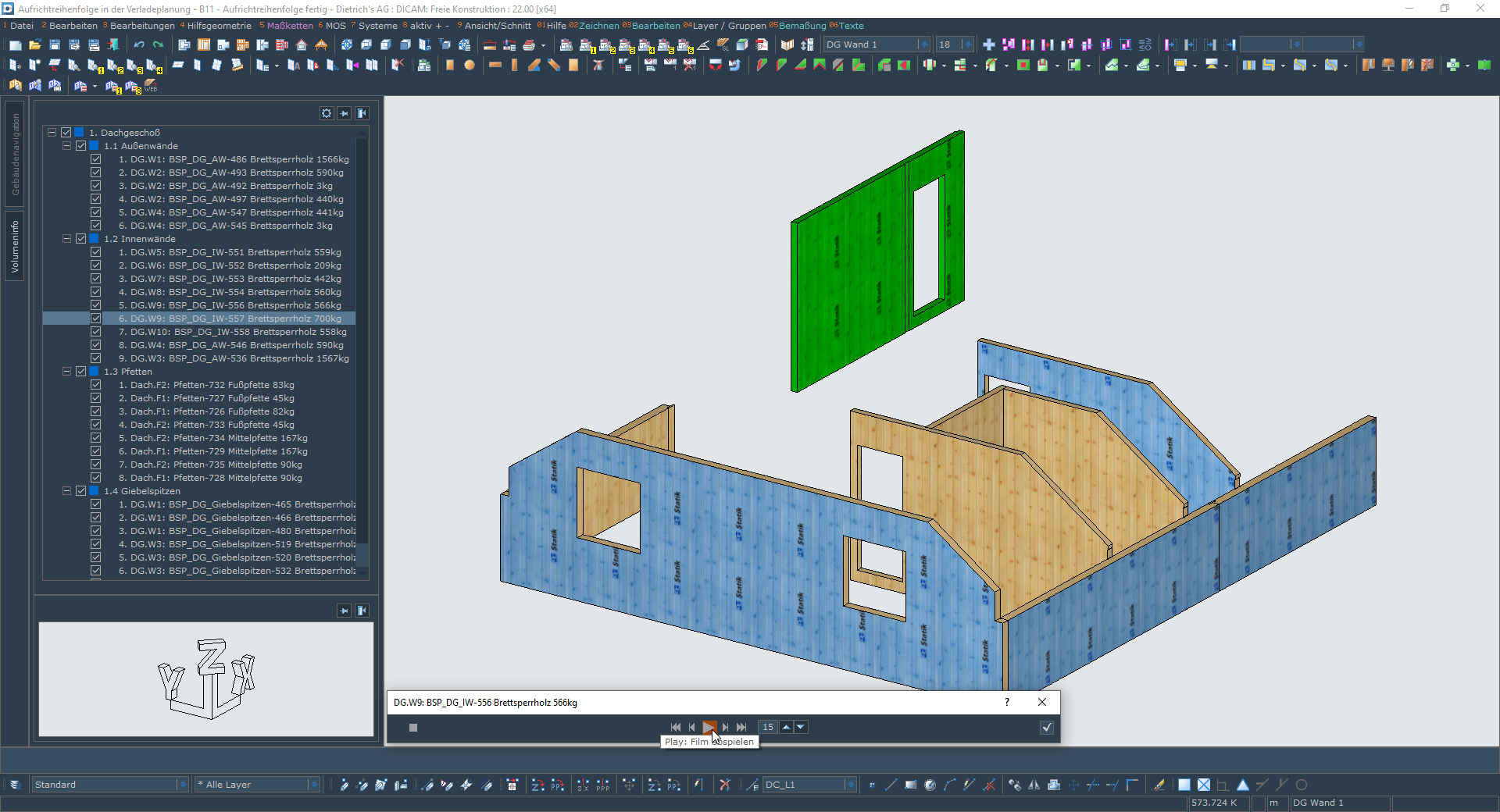
The assembly sequence can be edited very intuitively by graphically moving it within the tree-structure. At any time, there is visual control: currently in the tree-structure marked loading components are highlighted in the structure, already queued loading components can be differently displayed or hidden.
The assembly sequence is also adopted into the loading position. There it supports the loading process by automatically offering the loading components in the specified order for loading. The loading status of the loading component is also displayed in the tree-structure of the assembly sequence. Since loading can vice versa influence the assembly sequence, the assembly sequence can be edited here as well as in the building itself.
The function Present Assembly Sequence offers an ideal, ergonomic control of the assembly sequence. The procedure of the assembly process is shown in a film. The film can be paused and played back step by step or in sequence. The currently placed loading component is highlighted in the building as well as on the vehicle (loading position). It is thus possible to visually check whether both unloading as well as assembly at the construction site are possible as planned.
The result is the assembly sequence list, which can be created as a plain text or CSV file or via a special Excel transfer. With a definable information scope, the sections and the individual loading components are listed according to the assembly sequence. In the loading position, also vehicle, load carrier and loading level can be shown additionally.
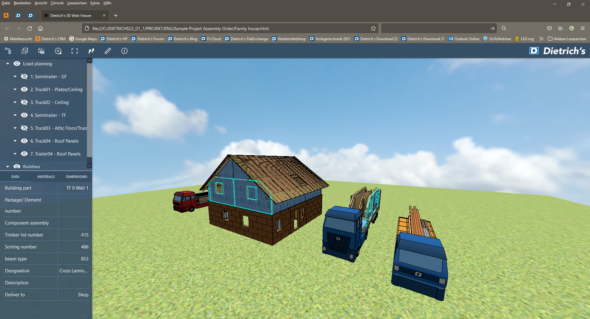
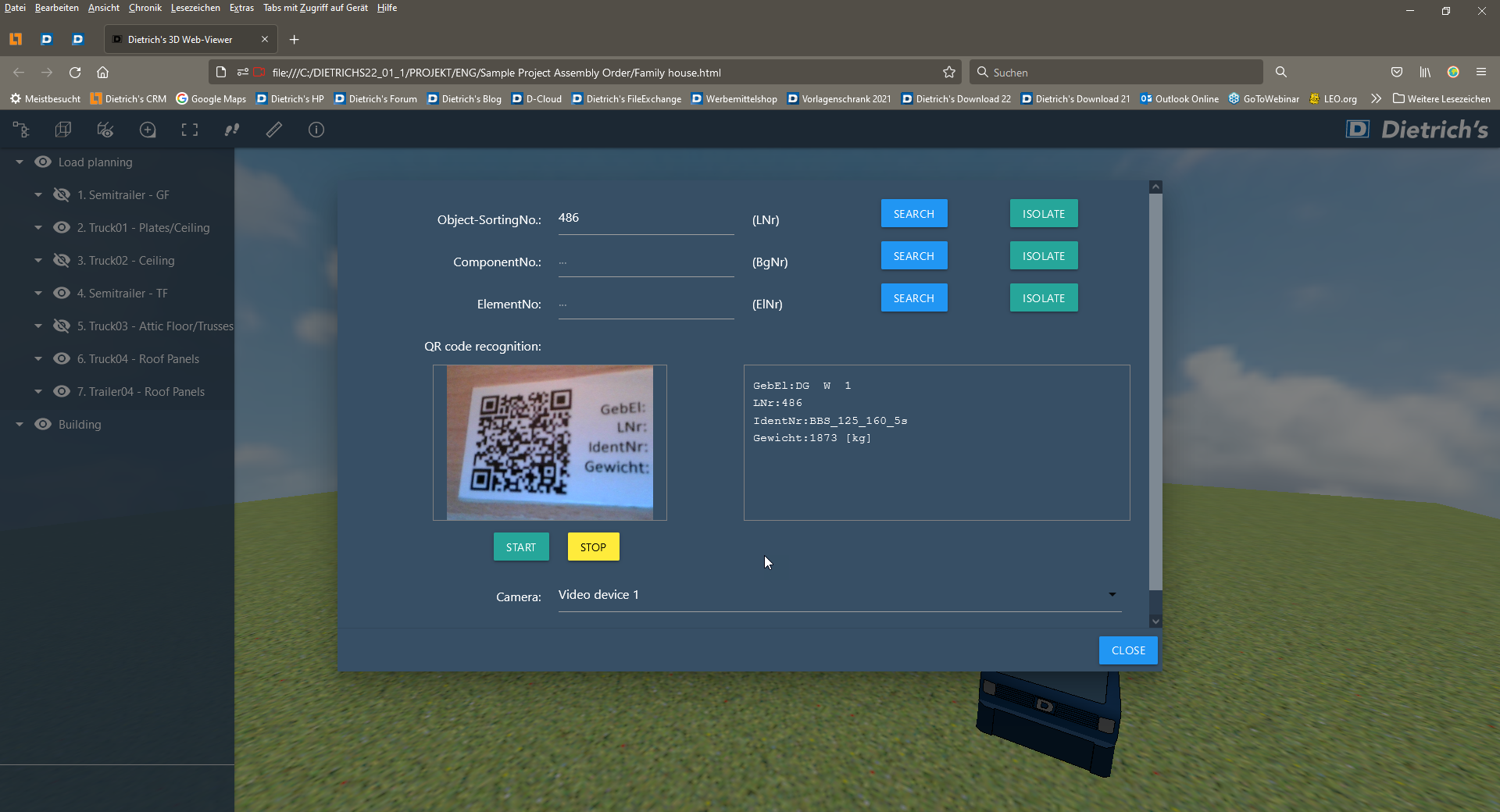
An up-to-date result for the use at loading and at the construction site, the assembly sequence is also exported for the 3D Web-Viewer (module required). Any tablet or smartphone can be used to display the position of the loading component on the vehicle and in the building. The loading component can be graphically clicked or searched for. For the search, it is possible to directly enter a sequence number or to scan a QR code located on the real loading component. Finally, the assembly process can also be played as a video in the 3D Web-Viewer and is in that way an optimal assistance for the operators during the assembly process.
Digital Communication
Digital Communication
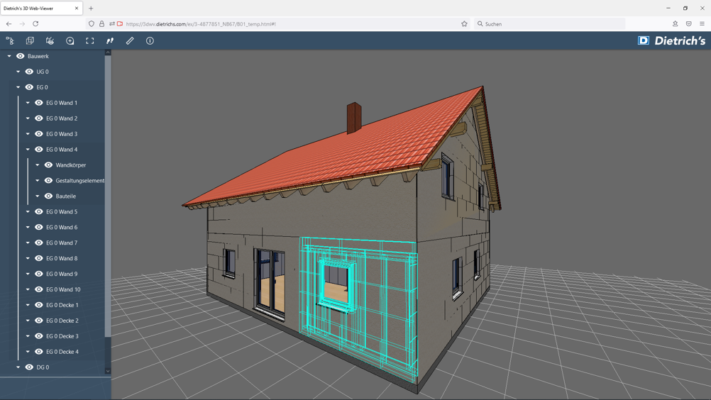
Dietrich's 3D Web-Viewer has already established itself as an important element of communication with building contractors, in one's own team or with other project participants. Easy to use and without installation, it provides clear 3D representations with building structure and component information. The V22 version of the 3D Web-Viewer also features interesting enhancements.
3D Web-Viewer, Cloud Service
The 3D web viewer is an HTML file that can be started in any web browser without installation. Being a service with a valid S&U contract, we offer the possibility of saving this HTML file in the Dietrich's Cloud with immediate effect and of working in the communication only with one link to this file. This provides an up-to-date solution for the following aspects:
- For security reasons, many mail programs block attachments with HTML files. As only the link is sent, the mail will now arrive safely. In addition, it will remain conveniently small, since only a link and not a file is being sent.
- On devices with iOS operating systems (iPhone) local HTML files can only be handled without graphics. This is no problem for the file opened via the link in an https connection. That way the 3D Web-Viewer is also usable on iOS operating systems.
For your safety and the safety of your partners, we also ensure that only original Dietrich's 3D Web-Viewer files can be shared in this cloud service.
3D Web-Viewer, Search, QR Code
The 3D Web-Viewer is used as an up-to-date tool during loading, and at the construction site. With any tablet the position of the loading component can be determined both on the vehicle as well as inside the building. In addition, further information such as dimensions and weight are indicated.
For this, the loading component can be graphically clicked or selected via a search function. In order to search, the run number, assembly number or element number can be entered directly. Alternatively, it is often easier to scan a QR code located on the real loading component than to type it in.
New Modules: Import- / Export Interfaces for STEP and IGES
The communication with other project participants is based on numerous interfaces. In steel construction, the STEP and IGES interfaces are very common. With the new STEP/IGES import interface, you can transfer steel constructions/steelwork designs into your planning. It can then be taken into account for further input or processed on. This data format is also used for exchanging data for TGA (technical building equipment) systems.
In reverse, the new export interface STEP/IGES allows transferring steel parts for manufacturing to your project partners. There, the structure/construction is incorporated into the specified metal construction programs and configured for the automated machines. Drilled holes, in particular, are exported so that they can be directly recognized as such in the finishing system.
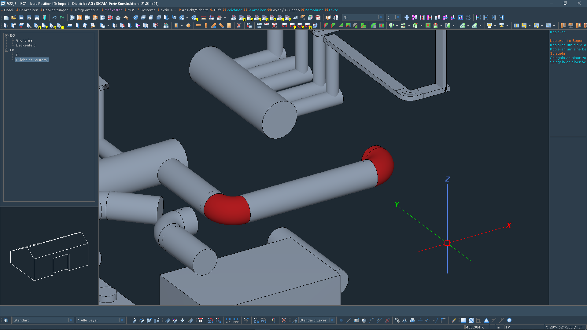
Surface Objects in the Building, Transfer from IFC
Especially in TGA, components are not mapped as closed solid bodies but only as surface objects. This way the sheet metal of the ventilation pipe is not created as a solid body but only as a surface object. In the corresponding interfaces, especially IFC, these components are also defined as surface objects. These surface objects can now be applied to the building structure and be managed there. This provides various advantages:
- The layout is clear, since it is possible to work with textures or hidden edges.
- They can be structured and displayed as single components: Assigning to building components, elements etc., changing such characteristics as ID numbers, colors, texture sets. Editing in plans (if necessary hidden and labeled) and in material lists.
As for imports, surface objects also enable a usable adoption of defective or poorly defined solid bodies.
In addition, surface objects can be used like other components in the building:
- copying and mirroring enable duplication
- via long/short the shape will be adapted which, for example, is important for ventilation pipes.
- saving them in the volume libraries will also make them available for other projects.
Ergonomics
New Module: Remote-Mode
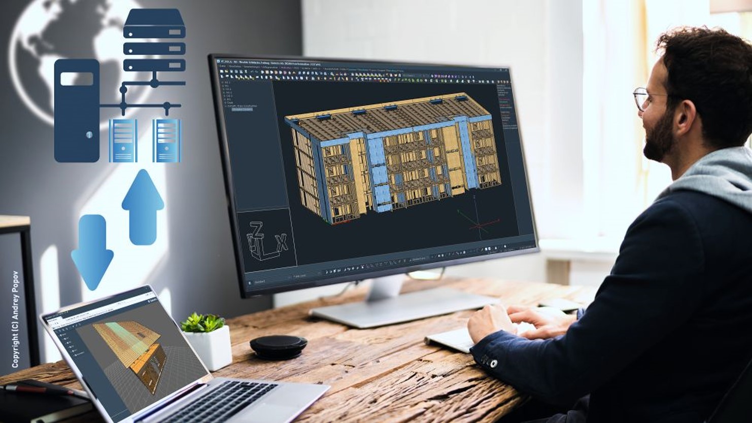
The requirements of recent years have given digitalization quite considerable momentum to almost all companies. Numerous timber construction companies have faced or are facing the challenge of ensuring their home-based employees to have safe access to company resources, Dietrich's applications and project data in order to be able to work productively.
With its now available "Remote Mode", Dietrich's software supports working in complex, computer and graphics intensive, virtual CAD environments.
Dietrich's applications are optimized for the technical features and high requirements of the remote environment. All applications and functions in 2D or 3D are optimally usable. That way, for example, it is possible to provide intensive CAD user guidance via mouse and keyboard with the highest possible user comfort and loss-free display. Benefit from powerful virtualization up to full display even on 4k monitors. Receive state-of-the-art display technology and high user comfort.
The remote mode enables central administration which in turn reduces costs and support. The advantages of central administration include reduced installation and maintenance time and costs, as well as greater systems stability and data protection. All Dietrich's applications, data and projects are kept up to date. A side effect is that the costs per CAD workstation are also reduced by means of virtual servers and virtual desktops.
We assist in planning and integrating Dietrich's software solutions into your virtual work environment. Dietrich's offers professional support in the implementation of licenses and creates the technical requirements for virtualizing future-proof CAD-based working from home workstations.
Palette Dialogs
A function defines what can be done with a software. The graphical interface of the function defines, if you enjoy it. With the new building navigation and palette dialogs, working in Dietrich's is greatly facilitated and you as user will enjoy it even more.
The palette dialogs can be positioned on the screen the way you want them to be. They always remain open, so the information is always available and can directly be edited. Should you have acute need for as much space as possible for the graphic, the palette dialogs can be hidden and also be shown again at the push of a button. As an alternative to the pinned position on the screen, palette dialogs can also be used as freely movable dialogs and in that way can also be moved to a second screen.
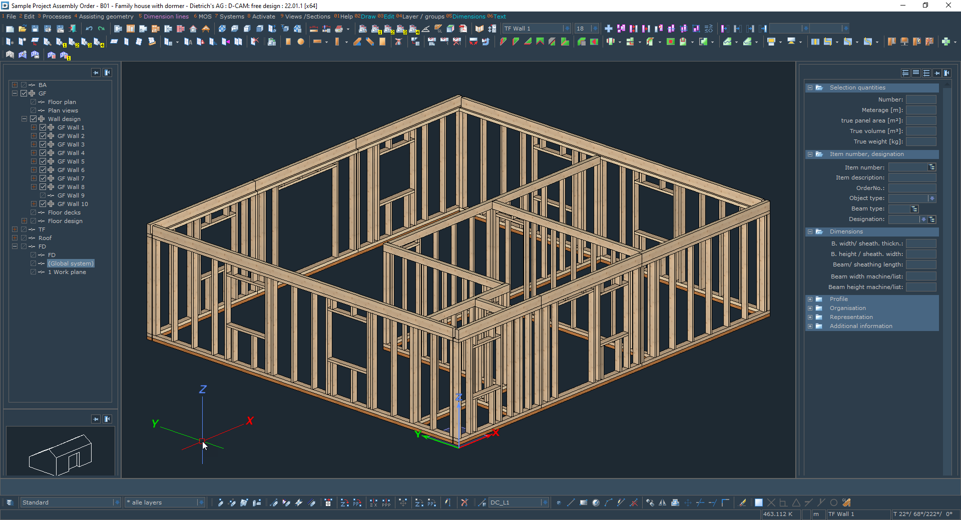
Volume Information
The new volume information is also structured as a palette dialog. The volume information for currently selected or activated individual components is accordingly permanently visible. A brief look is sufficient to see whether the correct component has been selected or the correct ID number has been assigned. If any change is necessary, it can be made directly and straightway in this permanently visible palette dialog.
In addition, details about the quantities for the components are displayed: amount, linear meter, sheating area, volume and weight. These permit a quick check of the plausibility of the selection. This also makes it very easy to quickly ascertain quantities for different purposes: how many linear meters of structural timber are in the wall? How much glulam (glued laminated timber) do I need for the purlins? Especially interesting is the weight indication when compiling packages: since the quantities are also during selection displayed in the function, you can track the weight while compiling so that you can very easily and directly take into account the maximum weight of the packages.
Speed due to new Do/Undo Process
Resetting entries in the so-called Do/Undo is an indispensable part of daily work. It is the simplest method of correction, is at any time available, is easy and always triggered the same way. The Do/Undo process has been completely revised and optimized in version 22. As a result, the function calls are much faster and are mostly instantaneous. The number of adjustable Do/Undo steps can now be set within the scope of practically useful applications as desired. The new process allows very comfortable working with Do/Undo, as it is up to 10 times faster, even in large projects.

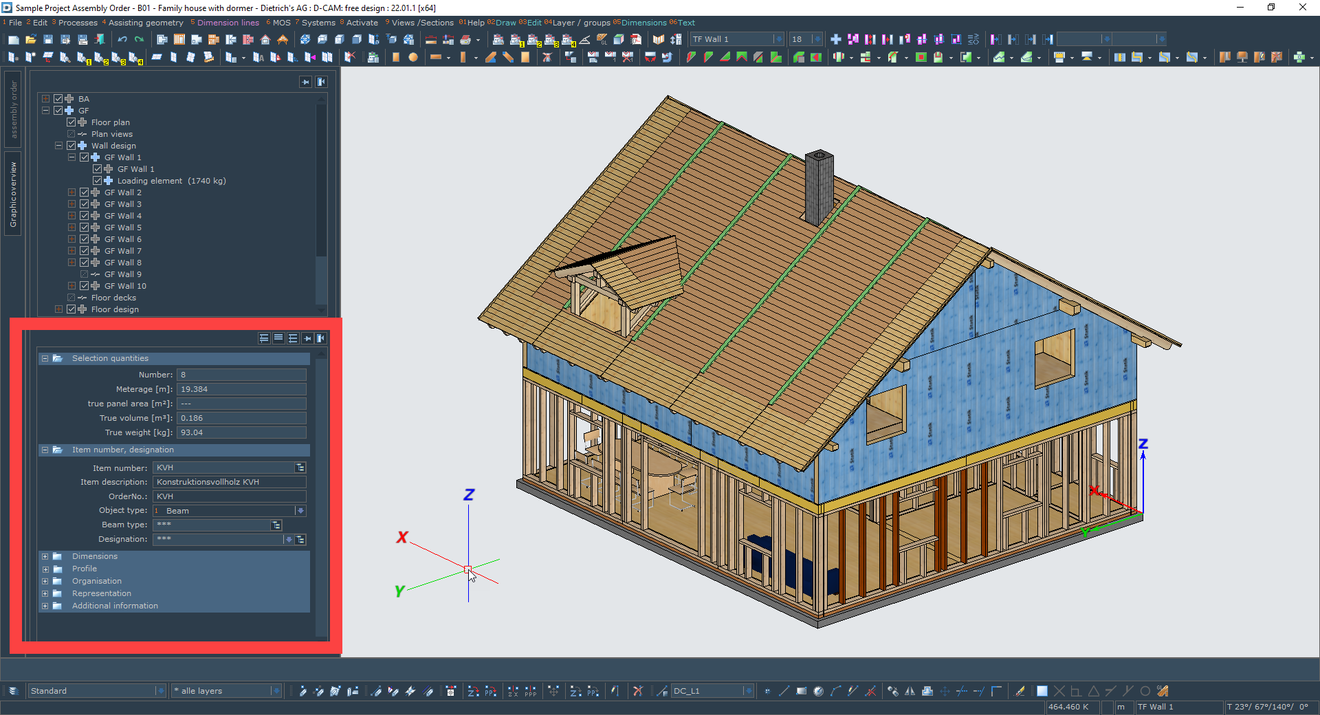
Building Navigation
Building navigation may be compared to the step from the map to the navigation system. With the new options such as preview, highlight, display/hide and activate, the building structure is revealed at an entirely new level.
This way it is now directly apparent what belongs to an element as a loading component and which individual components are supplied independently thereof. Should something have to be changed in the mapping, this can be triggered directly and targeted with the functions "Add component" or "Remove component".
By means of the functions for isolating, the current display can be reduced to the dimension precisely required for the current situation via the push of a button. If, for example, you want to do some detailed editing of a wall, it is optimal to only display this wall.
The strong, visual assistance along with the instant functions turn the building navigation into a focal element for processing large and small projects. This is the navigation system with which individual components or elements in production and at the construction site are at the right place at the right time.
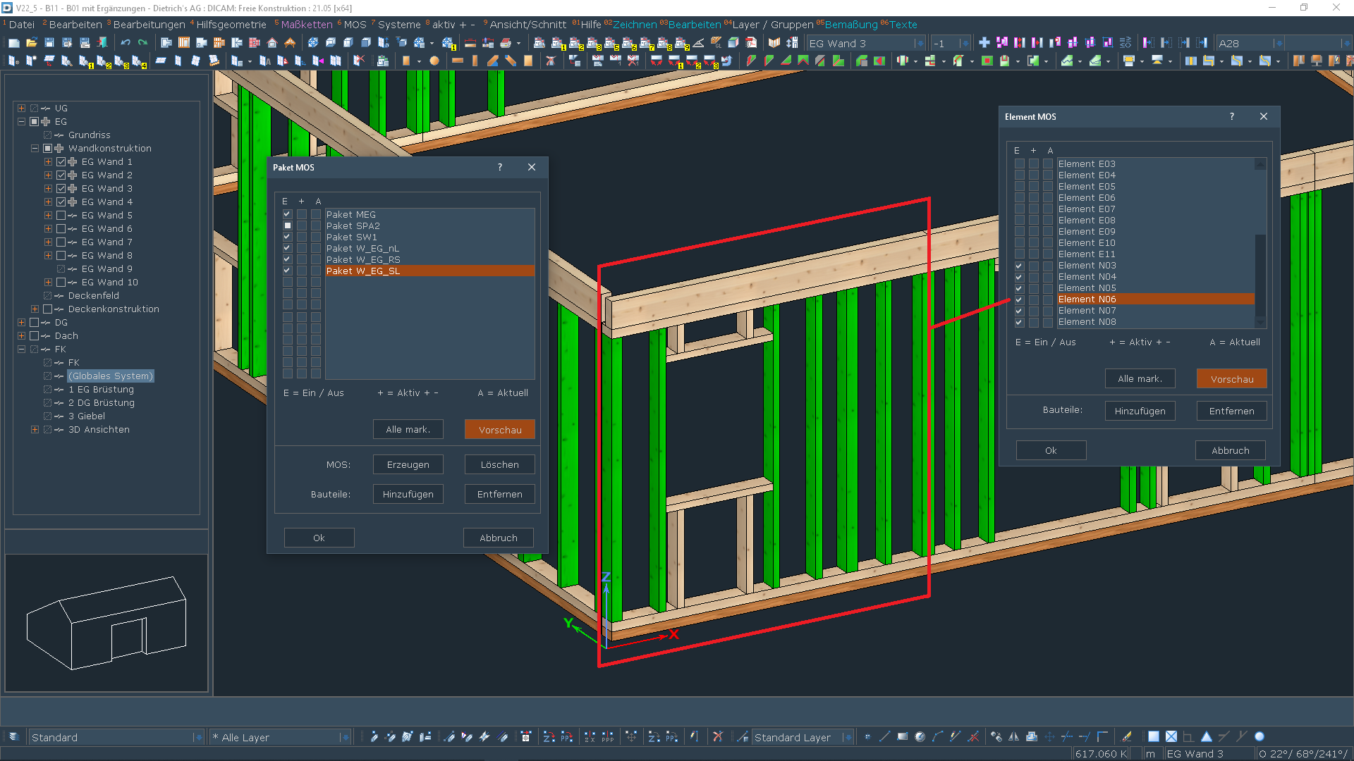
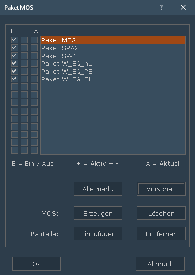
Elements, Packages
Elements and packages are important structures all the way from manufacturing to assembly. Elements define units that are pre-assembled during manufacturing and delivered to the construction site as elements. Packages are not preassembled, but define groups for process steps, for example the components that have to be processed on a specific kind of machine. The individual component can be part of a package for machine processing and later be incorporated into an element. Element and package mandatorily have to be independent of one another.
These structures are now provided separately and consistently throughout the entire system. In that way, you can coherently structure both the construction (elements) and the processes (packages). This provides you with a clear, consistent organization starting with the input throughout the results in lists, plans and machine transfers.