


Truss
...with different input methods and automatic load determinations
With the item type General truss you will calculate 2D constructions including the wood connections. Different input options allow you to easily enter the design to be dimensioned. Various options are also available for load determination.
- Draw Truss
- ... through nodes and axes
- ... by manual component input (as in a CAD software)
- ... by using parametric frameworks
- automatic determination of the engineering system
- Introduction of loads by taking over rafter positions and roof positions
- Load determination for roofs
- Verification of timber construction connections in one and the same static position
Three different options available DC-Calcs for truss input:
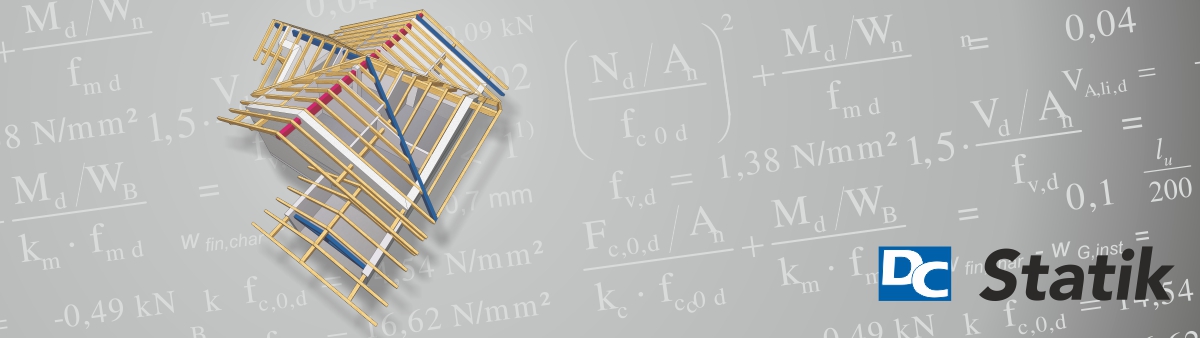
Input of nodes and axis
This input method is used to position the nodes of the truss and the component axes between them. The nodes and bars can be defined in tabular form or simply by graphically tapping drawing elements, for example, imported DXF files. Finished truss constructions can be changed in length and height by a shift function of the nodes.
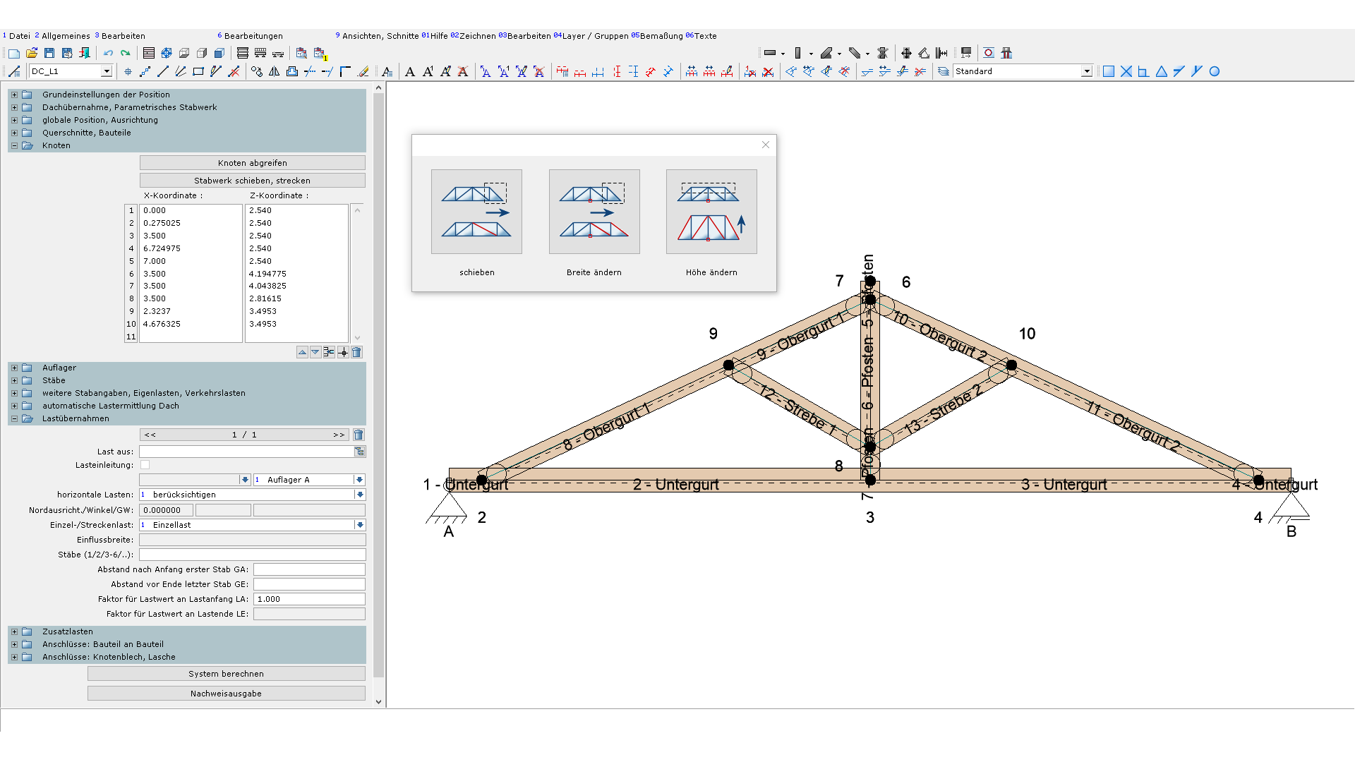
Manual input of component
A much simpler and carpenter-friendly method is the manual component input. The components are positioned as in a CAD software. Static nodes and component axes are automatically determined by DC-Calcs. Threshold values can be used to influence the automatic abstraction of the engineering system. For example, by specifying a maximum distance, nodes that are close together can be unified.
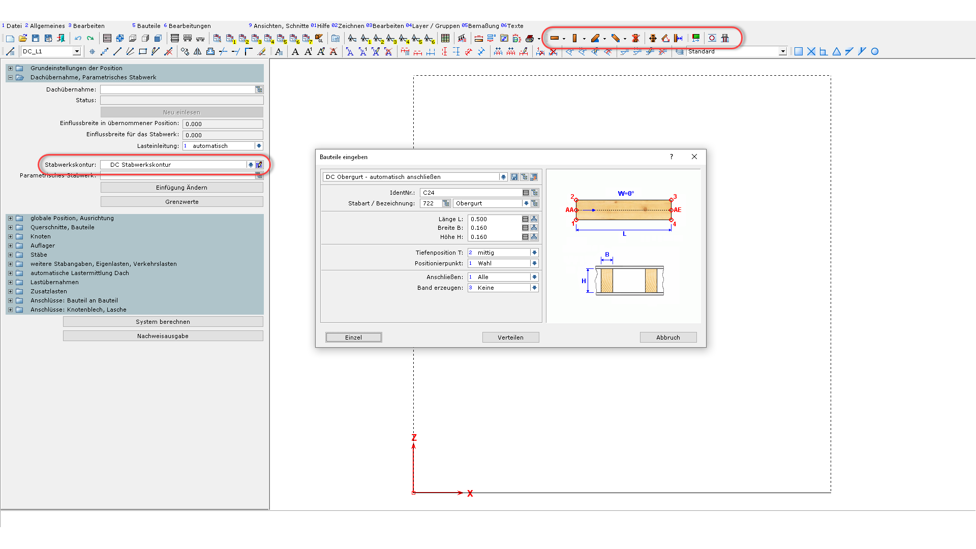
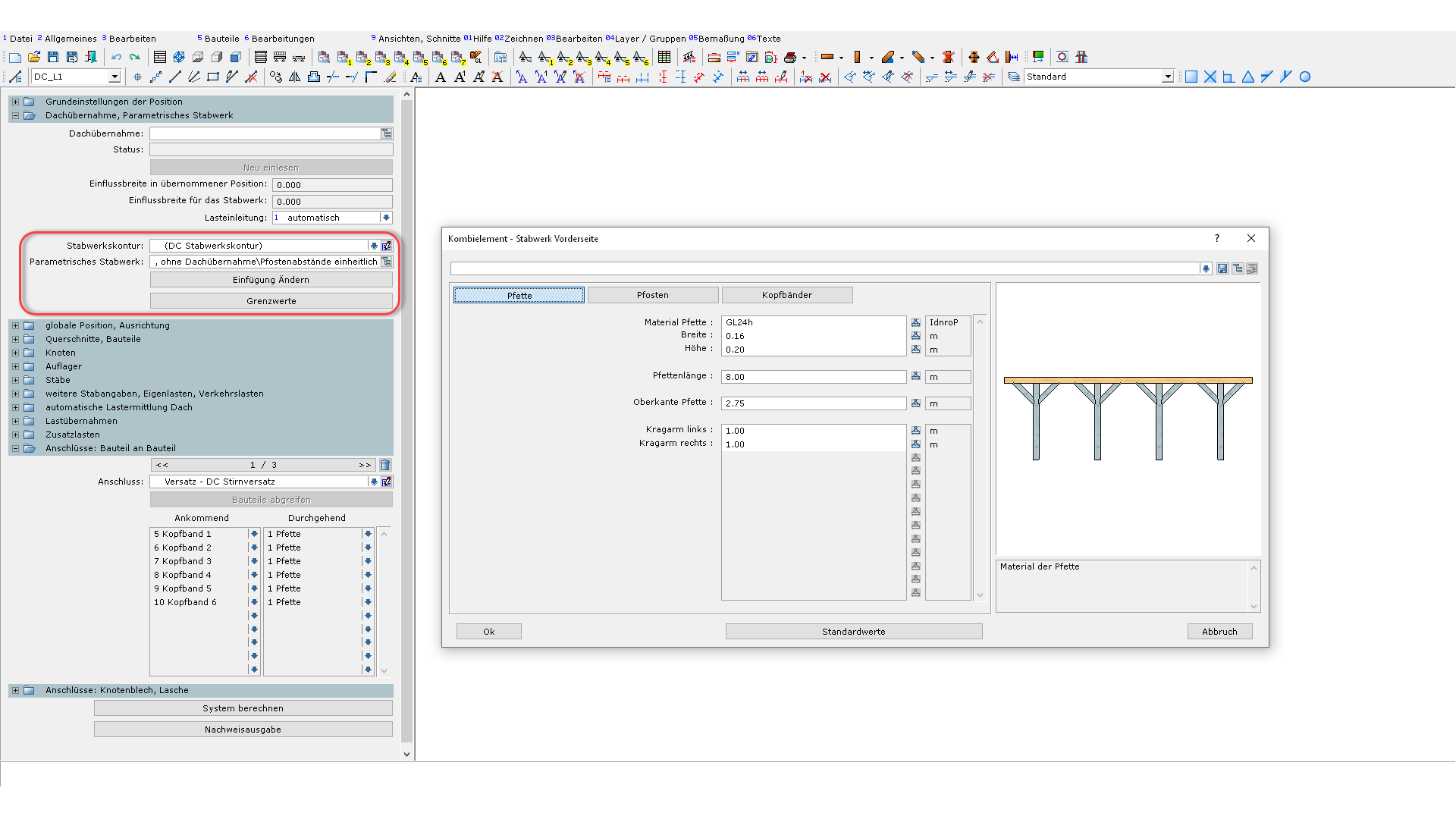
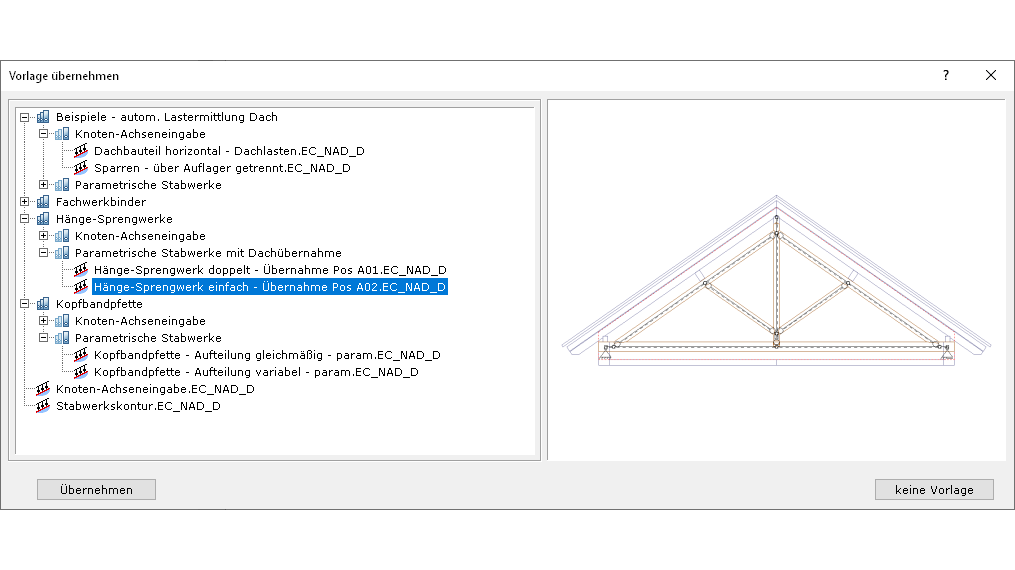
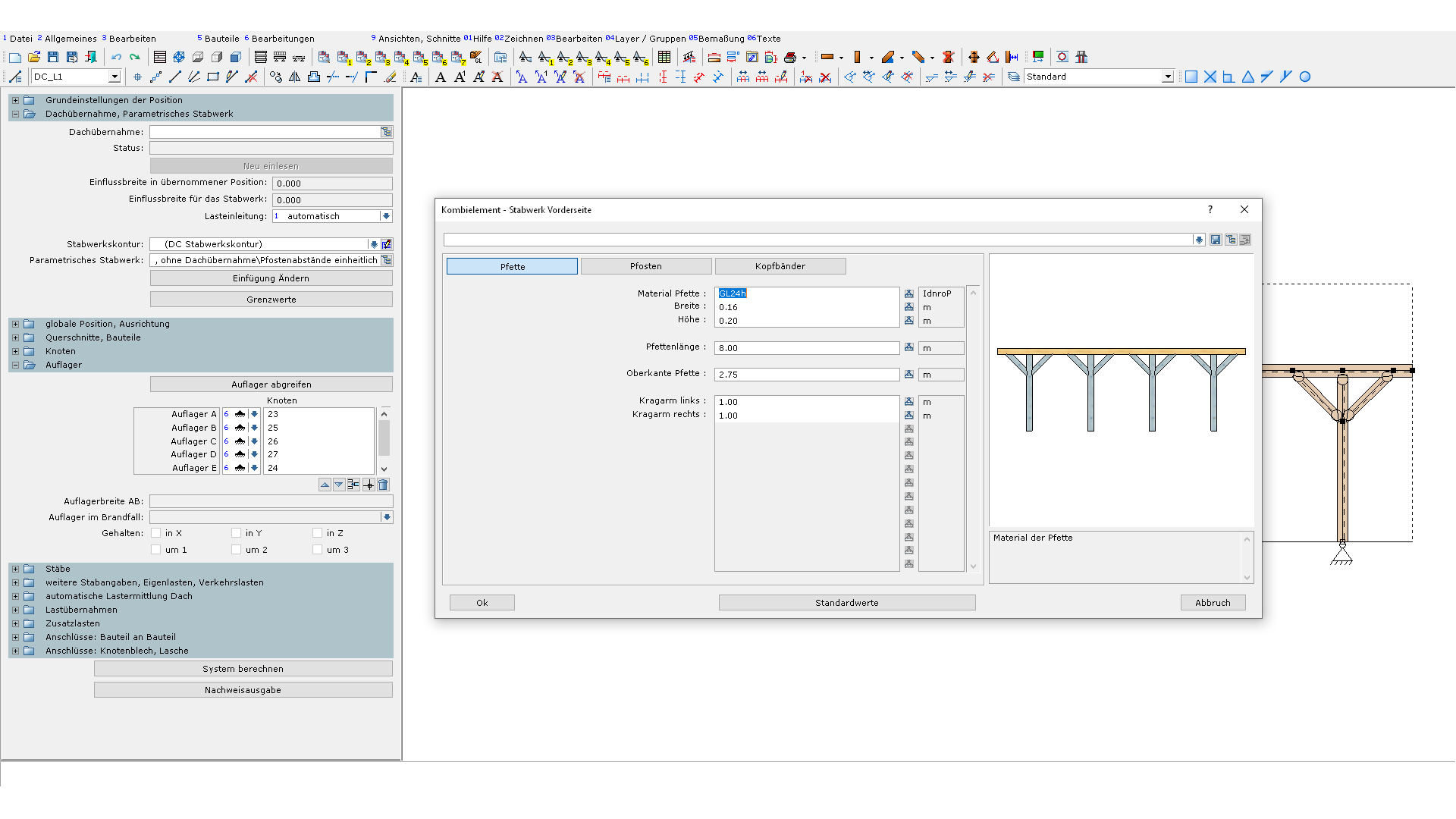
parametric trusses
Parametric trusses are available for regularly recurring constructions. For example, various suspension sprinkler systems and connectors are stored, which can be adapted to any situation. Individual truss designs can, of-course, be created as parametric trusses by the user himself or provided from us as part of our range of services.
Loads in the framework
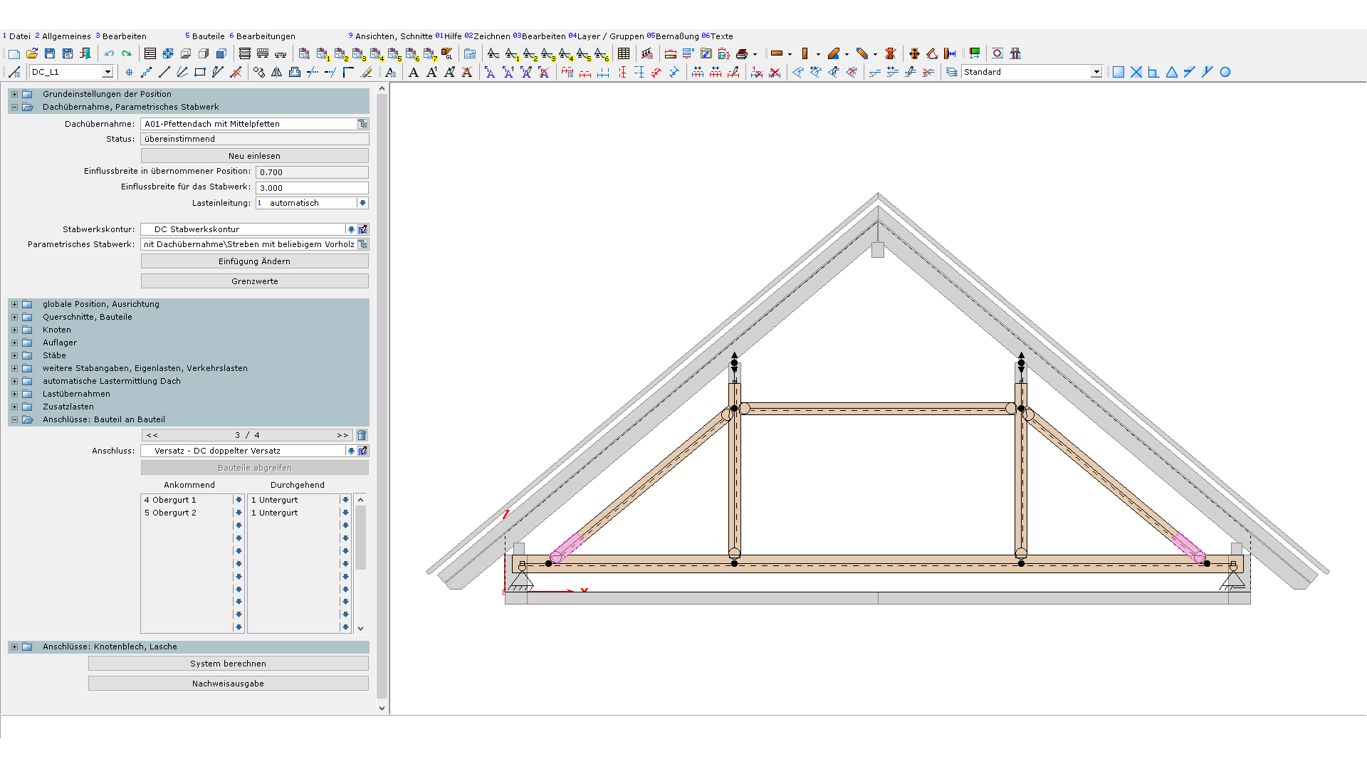
In order to transfer loads from an existing rafter construction or roof construction to a truss, you import them via the roof transfer in the framework. You can then construct the truss construction with the manual component input or with parametric trusses, based on the acquired roof components.
For truss constructions that directly support the roof cladding, the roof loads can be determined automatically by the software similar to the calculation of rafters and roof constructions. For this purpose, the components forming the roof cladding are selected in the corresponding input group.
Naturally, you can always transfer loads from other structural positions and define any additional manual loads.
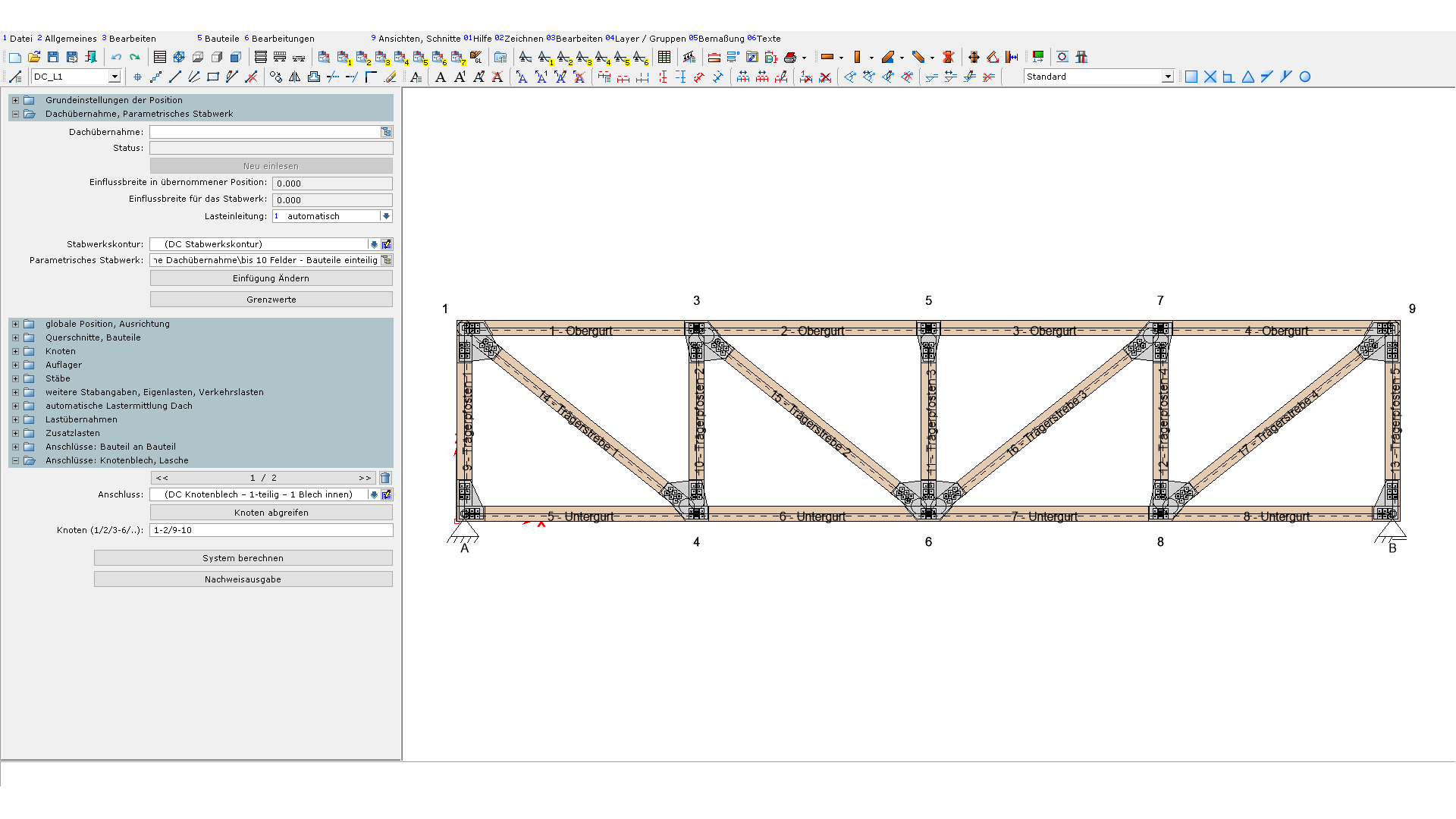
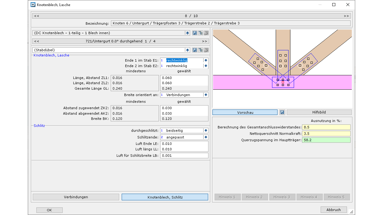
Wood construction connections in the framework
Another highlight of the framework are the integrated wood construction connections. Components can be connected with tenons, offsets, tie connections, slotted plates and butt straps. The design of the framework structure including the connections is thus carried out in one and the same engineering position.
Connection to Dietrich's
Framework positions with roof transfer can be used in the Dietrich roof design software. These framework positions can be used there like profile positions. It is also possible to adopt the rafter and plate dimensions from the engineering positions. In addition, you can transfer the completed pre-dimensioned engineering trusses including the wood construction connections to Dietrich's design software.


