
Dietrich's V24
The most important Innovations at first Sight

Dietrich’s designs processes and provides software solutions for timber construction along the entire value chain for the trade sector, the construction industry and globally operating industrial companies - in a way that is always needs-based, ergonomic, customisable and future-proof.
The new Dietrich’s TeamSuite is the ideal digital tool for the collaboration between a project team. Be they planners or work schedulers: an unlimited number of team members can access the central project simultaneously. If they are working on a structure at the same time, this is implemented via the central position. You can therefore, for example, divide projects according to different planning stages: (submission planning, work planning, design, ...) or by key construction points: (walls, ceilings, roofs, ...) and work through them at the same time as a team.
An important part of the user-friendliness is the program’s performance, in other words the speed at which it reacts. When the program hesitates, not only does this waste time but it also makes the user tired. In Version 24 we have paid particular attention to performance and optimised the speed of many actions. This relates both to fundamental actions such as changing the model area or accessing functions where every second counts, as well as to more extensive calculations, where every optimisation step has great significance.
Planning
NEW! Plans, dynamic plans
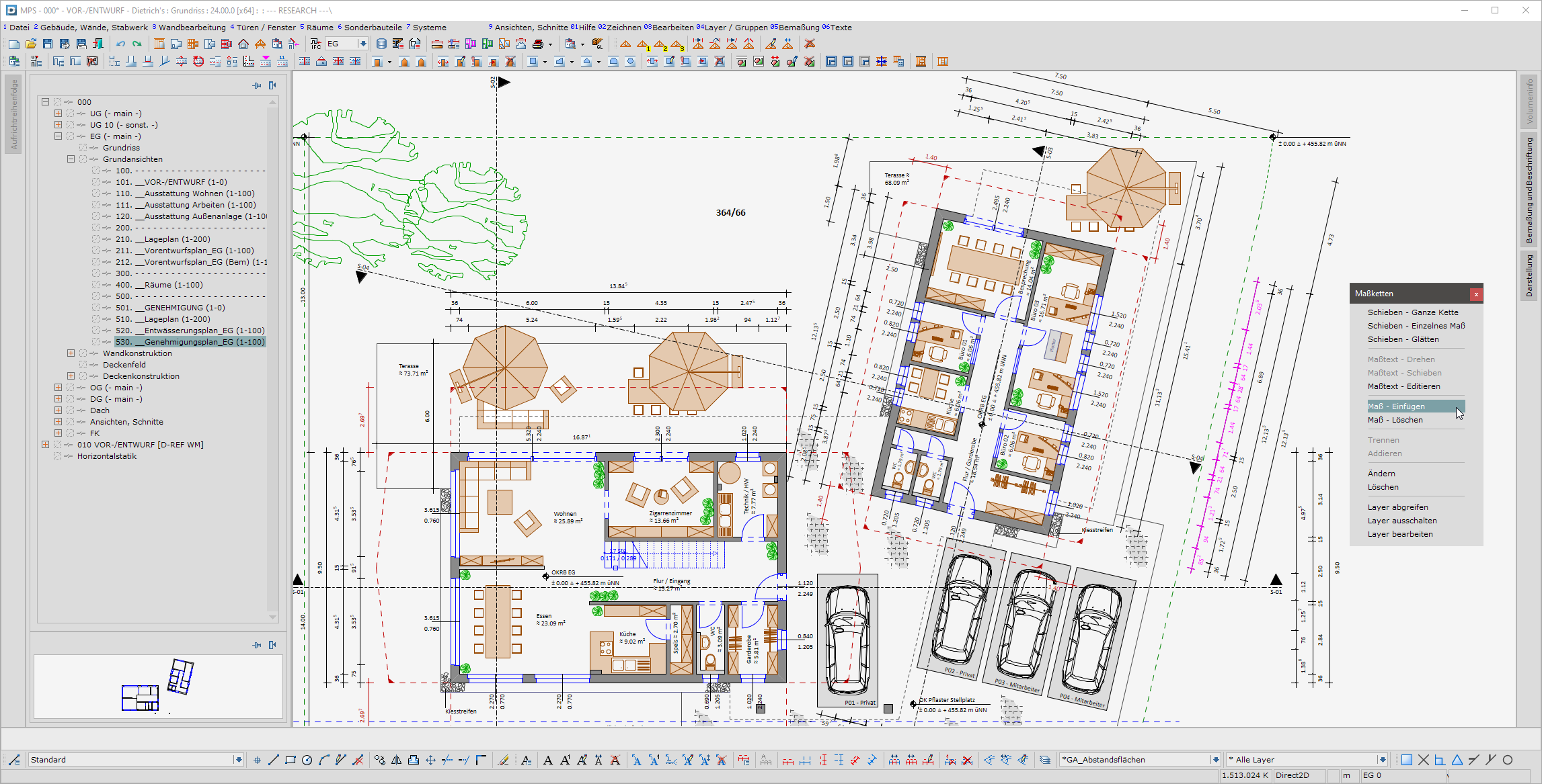
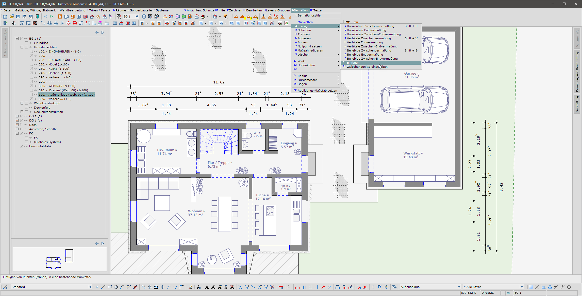
The automatically generated dimensional chains deliver many dimensions at the press of a button and save on manual input. These automatisms are being constantly improved, but do not always cover all cases in an optimal manner.
With Version 24, the functions used for adjustment purposes have been widely extended by automatically created dimensional chains. It is now possible to not only delete individual dimensions, but to also add dimensions, edit dimension texts and change entire dimensional chains. All changes are preserved even after recalculating the dimensioning. As a result, even the last few per cent can now be covered conveniently, quickly and permanently in complex situations when the automatic result is only 95% correct. Whether it is regarding the building, the profile or the plan, the intervention options are now available in all programs and for automatic dimensioning steps.
NEW! Planning, ground views, views, sections
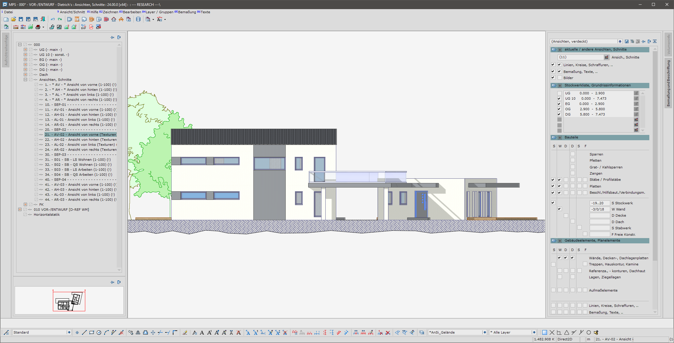
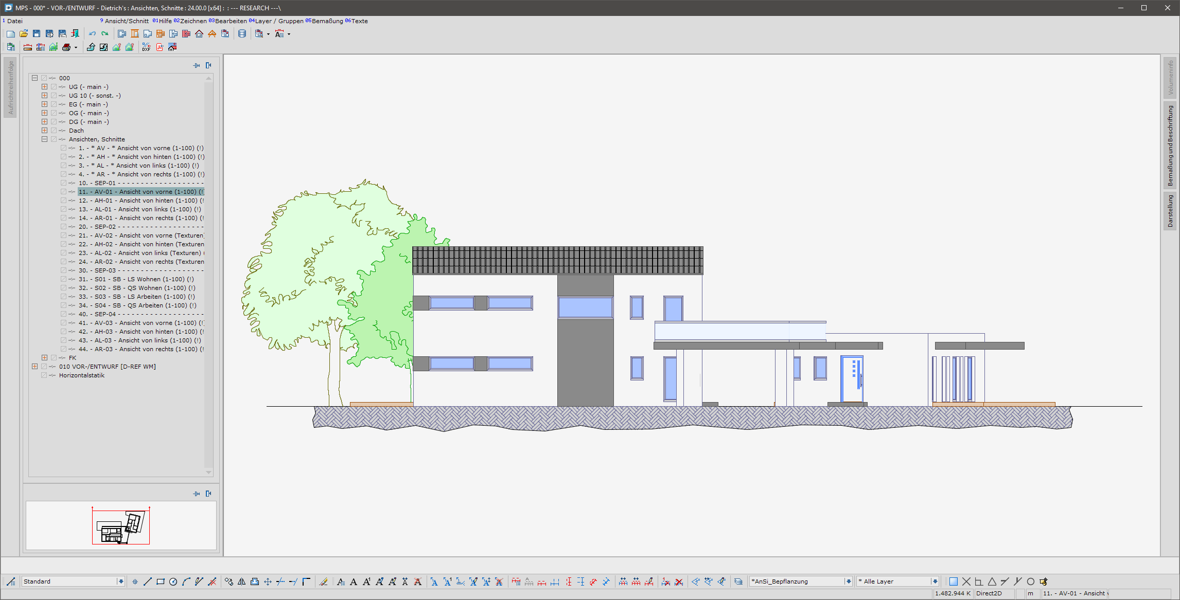
The basic views, views and sections have shifted the preparation of the plans heavily towards the building structure. This method of working is very dynamic and clear. The additions to V24 make this method even more efficient:
- In the storeys, planning elements such as lines, circles, texts, dimensioning steps etc. are associated with the “floor plan” or one of the ground views. This association allows planning elements to be specifically switched on or off. All planning elements of a storey can now be edited in the “floor plan” and every ground view of this floor can be edited too. The adjustment process is even faster and more convenient.
- Separate, individual layer settings for ground views, views and sections: In a building, lines for water pipes, for example, should generally be shown in grey. In certain ground views, however, they are of particular importance and should be blue. The lines for the pipe routing should not be entered twice, however, To enable this, the “separate, individual layer settings” for ground views, views and sections have been introduced. The same line can thus be shown differently in each ground view. The fact that this line is then only present once not only saves time during the input stage, it also prevents errors when subsequent adjustments are made.
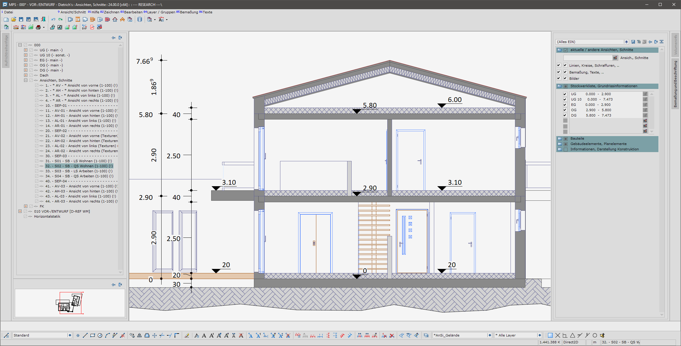
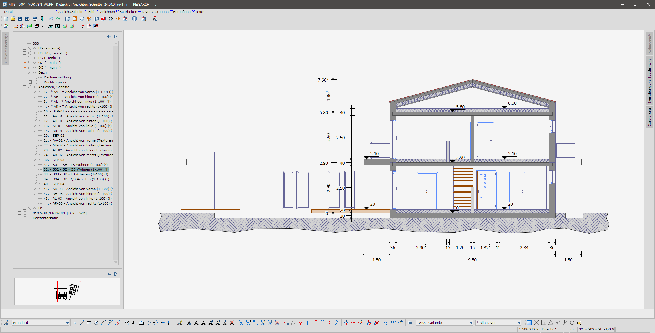
Views, sections from roof and DICAM
The new “Views, sections” model area, which was introduced with Version 23, is very popular. It includes functions to generate sections, section areas, section sequences and views. Once set up, informative views and sections can be created without much extra work. With Version 24, creating views and sections is now even easier and more user-friendly. Sections and views can now be created directly from the DICAM, roof construction and roof support structure model areas. The current display is automatically adopted for the new section or new view.
Planning elements in general
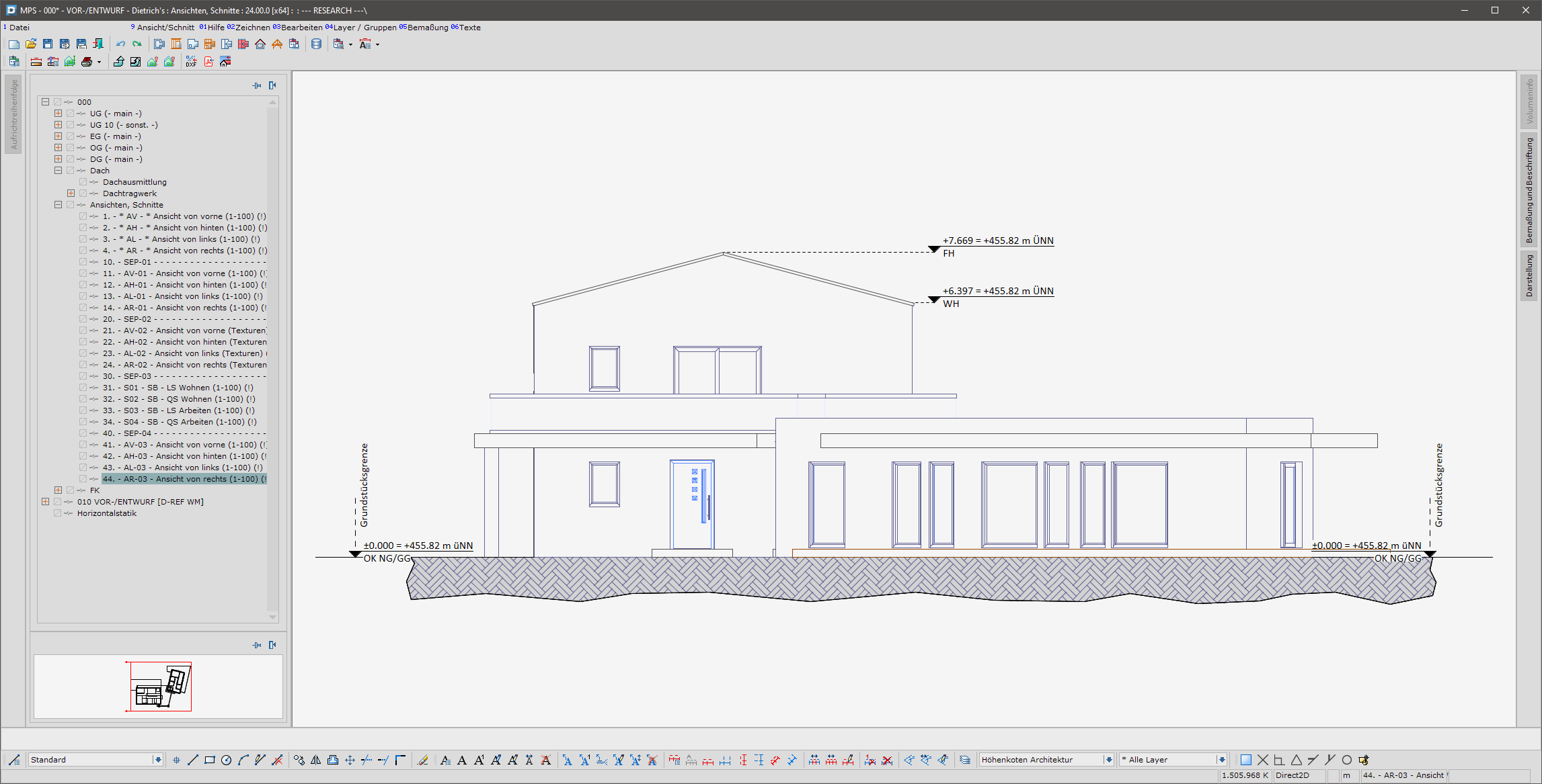
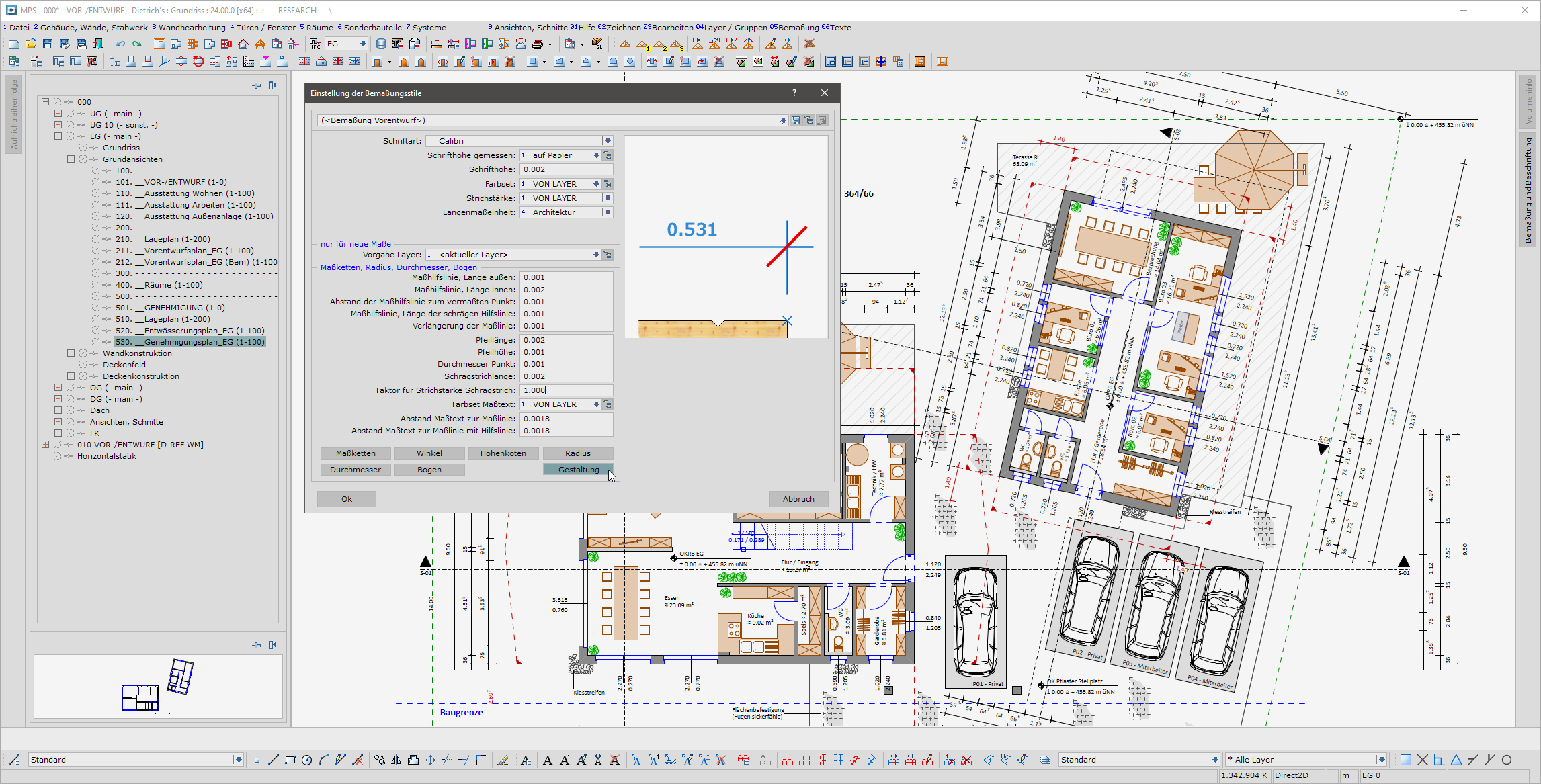
Germany, Austria and Switzerland have different rules for the line thicknesses in dimensioning steps in construction. To take account of these rules, the settings for dimensioning styles has been widely extended in Version 24. Besides the length of dimension extension lines and the line width of oblique strokes, the height of triangles for height coordinates can now be adapted directly to the dimensioning style. The dimensions can now be shown simply and at any time in a country-specific format that conforms to standards.
Editing hatchings
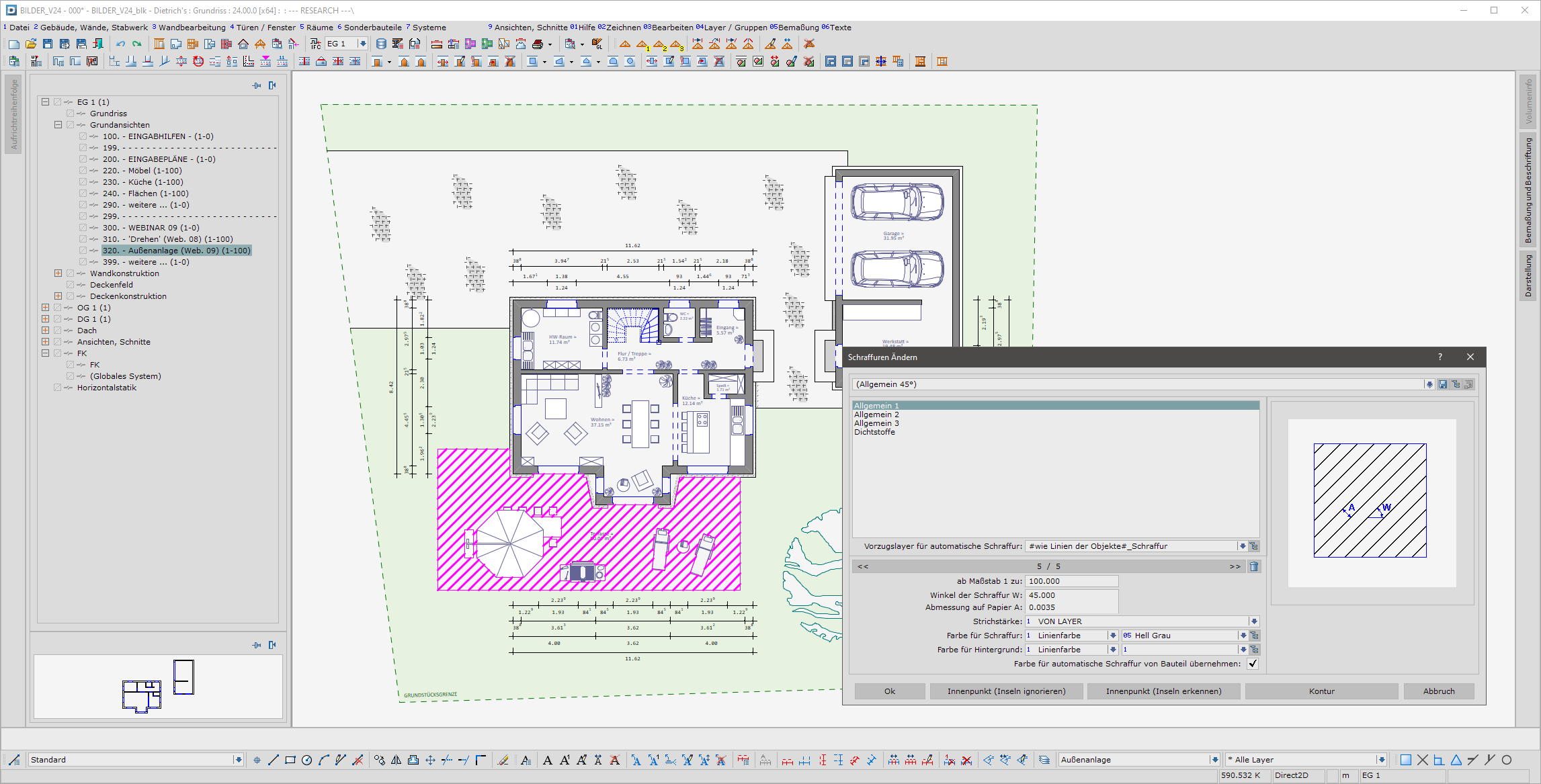
During the planning and implementation of a construction project, adjustments and changes constantly have to be made. In order to be able to do this quickly and flexible in the hatching area too, the ‘Change’ function has been revised. From Version 24 onwards, existing hatchings can simply be recalculated. This intuitive and user-friendly function avoids time-consuming new inputs. With just a few clicks, a hatching can be conveniently adjusted to new situations in the construction plans. If a recalculation is not enough, this is also no longer a problem. Using the new ‘Change - Contour’ functions, the hatching polygons can be quickly and precisely adjusted.
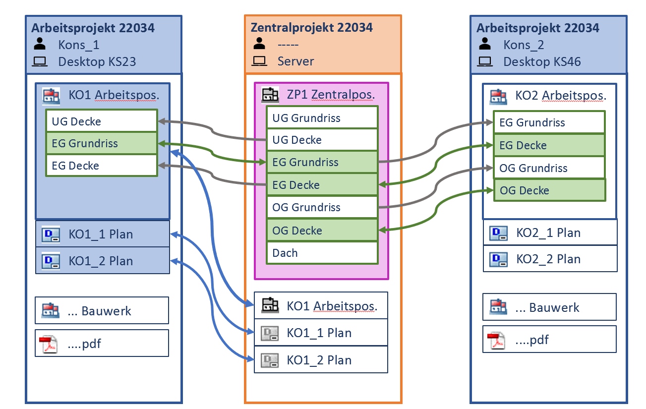
NEW MODULES: Central Project, Central Position
Many projects are worked on by a team. The roles and allocations are typically the result of:
- various planning phases: submission planning, work planning, design, ...
- key construction points: walls, ceilings, roofs
- such big projects that each area must be worked on by several team members
To work smoothly through the project, the team needs
- the option of simultaneously working on the project or also structure
- organisation of the allocation to the team members and access to the project areas
- overview of how up to date the data used is and convenient data comparison
The new optional modules of central project and central positions provide the infrastructure for the teamwork according to these requirements.
- Unlimited number of team members can access the central project simultaneously. If they are working on a structure at the same time, this is implemented via the central position.
- The owner status is used to secure access to the positions, files or parts of the structure. The authorisation is transparently visible for every person involved.
- It is possible to work in the work projects undisturbed, regardless of how many other team members are currently active. And offline mode allows work to continue, even when no network is available.
- Obvious symbols and detailed information always tells you have up to date the data is.
- Sophisticated synchronisation functions allow work to be carried out conveniently even in large-scale projects.
Central project and central position support the team as the optimal infrastructure for the division of work and to manage large projects.
Construction
Wall, ceiling, doors, windows, niches: adopt
During the course of the project and the input of the building, the ceilings, walls, doors and windows are designed. At this stage, designs are adjusted, heights determined and additional attributes added. If other building elements are added, these can simply be adopted as a template. A new wall is therefore created by adopting the design, heights and attributes of an existing wall with the click of a mouse. This is easier because these properties do not have to be entered or determined again. These can also be re-used for new elements on another storey or in another structure. The wall that proved successful in an earlier project can thus be immediately used in the current project.
Move, rotate wall
Subsequent changes and adjustments make up a large part of the day-to-day work. When it comes to walls, this often means that they need to be moved or rotated. The reasons for this may be new decisions made by the client or inaccurate initial plans or measurements. The revised move and rotate functions for walls are intuitive and efficient, making the work required much easier.
Component drawing libraries
A well organised plan is the best reference for a draughtsman or carpenter. At all work phases, ideas, solutions and information have to be set out clearly and comprehensively. The component drawing libraries are an important tool, which has been further extended. Alongside design elements for outdoor facilities and the area of fitness and leisure, bolt and screw anchors as well as sealing screws among other things have been added for the construction process.
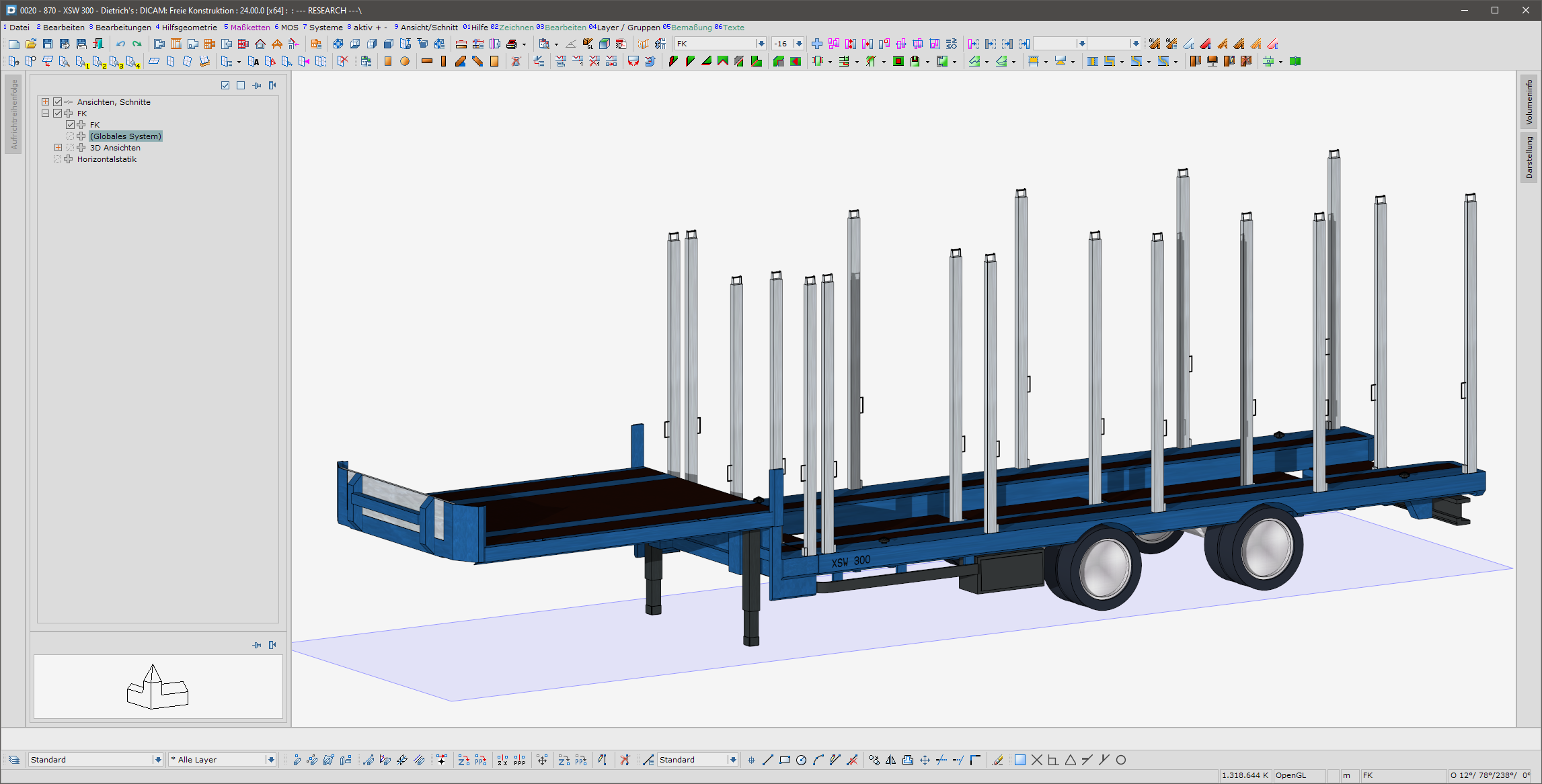
NEW! Loading aids
Whether it is a case of building detached houses with long journeys, adding floors to inner city buildings or implementing major projects in multistorey timber construction – transport and logistics are becoming increasingly significant in the construction industry. That is why the Dietrich’s load scheduling function was introduced with Version 21 to cater for this important area. In cooperation with the company Auwärter, selected loading aids such as swap bodies, trailers and articulated vehicles are now provided in our libraries. The realistic loading capacities and clear identification of loading aids guarantee a smooth loading process.
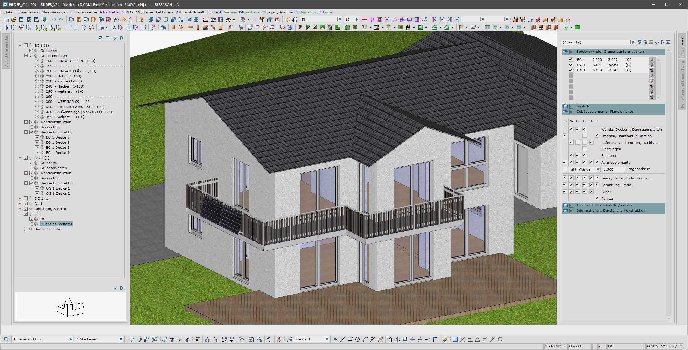
NEW! Balcony railings
Depicting the construction project in an appealing manner is very important during the design phase. In this respect, balconies and their railings play a prominent role for the outer appearance of the building. The new combination element for balcony railings allows modern and appealing railings to be created quickly and simply. Two types (front-mounted and surface-mounted) can be combined with various field design options. Generating units installed on balconies can also be depicted.
Combination element for electrical installations
Comprehensive planning in timber construction also includes taking the electrical installations into account. Working closely with the developer, the distribution and type of power sockets and switches is determined in the planning stage. Holes for sockets are also drilled according to the agreements made. Cable ducts must be made, whilst empty sockets and switches need to be ordered. The new combination element for electrical installations offers an efficient yet user-friendly input option here. In one step, up to 4 switch groups lying on top of each other, each with up to 5 elements per group, either horizontally or vertically aligned or mixed etc., can be created. As is usual with all combination elements, it is possible to make changes at any time without inputting new data.
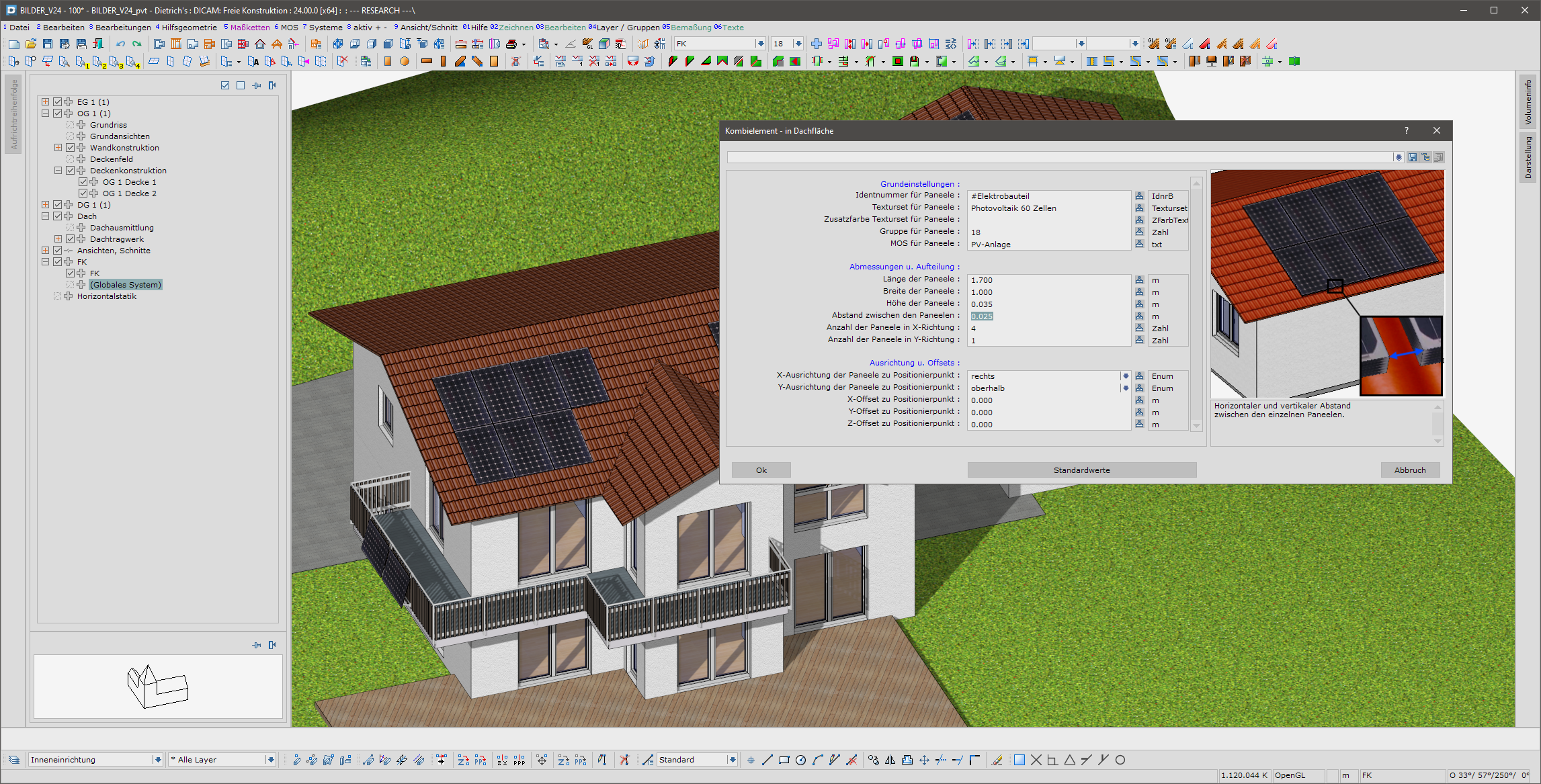
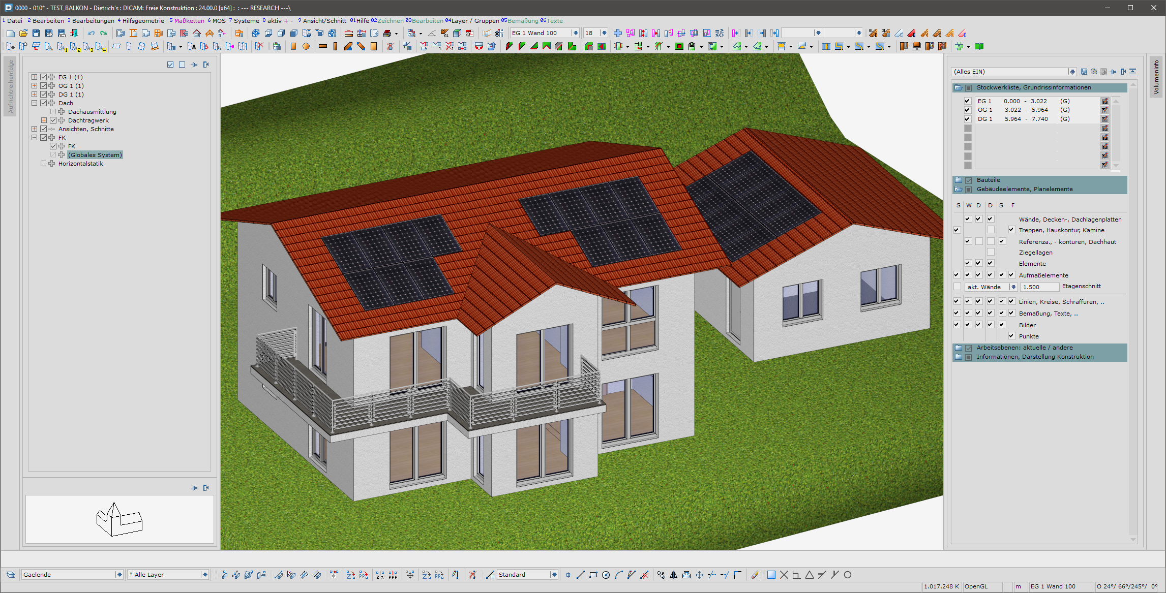
Combination element for photovoltaics
For new builds, a photovoltaic system is almost indispensable and also affects how the building looks. To give a realistic impression, this should be depicted with the rest of the drawings. The new “photovoltaics” combination element provides a quick and convenient solution for this.
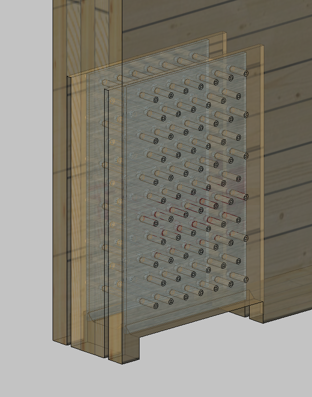
Visualisation of the drill holes: uncut drilling volume
Drill holes are used in many details and are very important for the design. The creation of drill holes is the most realistic method of depiction but puts a huge strain on the system, and only showing the drilling axes gives an inadequate impression. The new method of depicting the uncut drilling volume shows a complete picture of the design. This depiction is available in OpenGL in both the wireframe model and in a transparent, textured version. The system’s performance is preserved at the same time, as the calculations are carried out faster than for drill holes. This allows work with drill holes to be done intuitively and ergonomically.
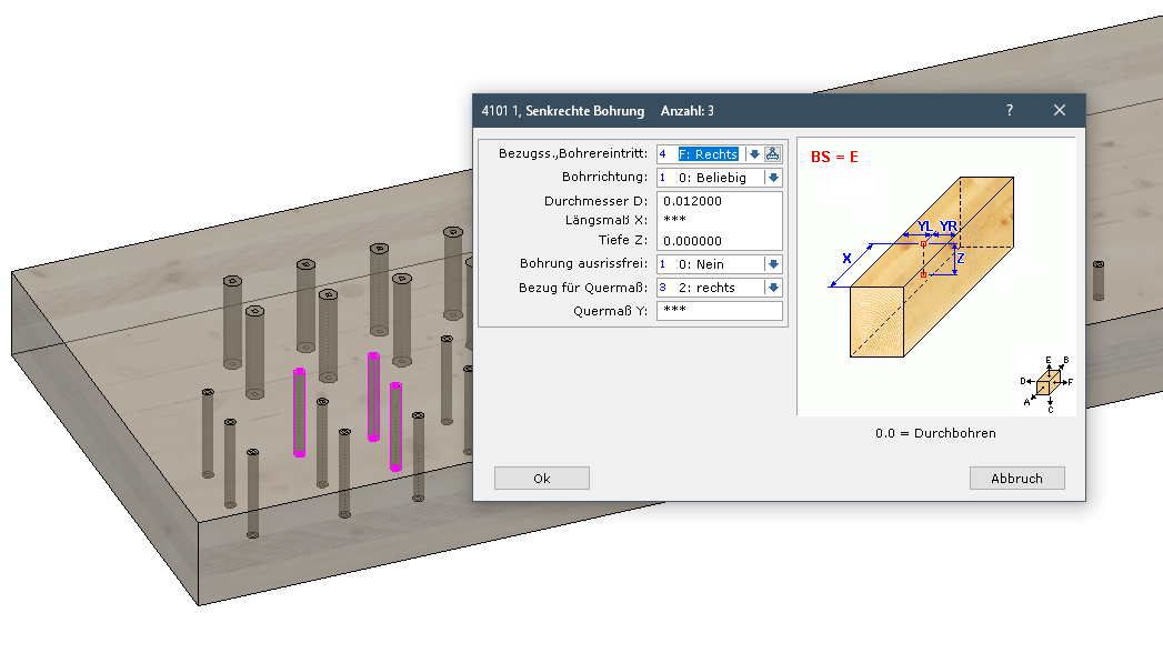
Revising several drill holes
Revising the drill holes is now much simpler. Changing hundreds of drill holes because of an incorrect diameter no longer means hours of rework, but instead can be done reliably and conveniently in just a few minutes.
- The drill holes can also have different parameters and belong to different structural elements.
- The selection is made by individual selection, selection with a window or a polygon.
- Selecting “Similar” offers special options: All drill holes are found that are similar to the drill hole first selected. What similar means can be set dynamically: Firstly only the same diameters was selected, but you can see from the proffered drill holes that this must be limited further. In the filter for “Similar”, you now add that the reference side must also match and only those drill holes that match in terms of diameter and reference side are proffered.
- Different parameters can be retained (typically e.g. cross dimension) or overwritten with a value (typically e.g. diameter)
- The linear and cross dimension can also be changed equally with a relative value and the drilling pattern can hence be moved.
Digital Communication
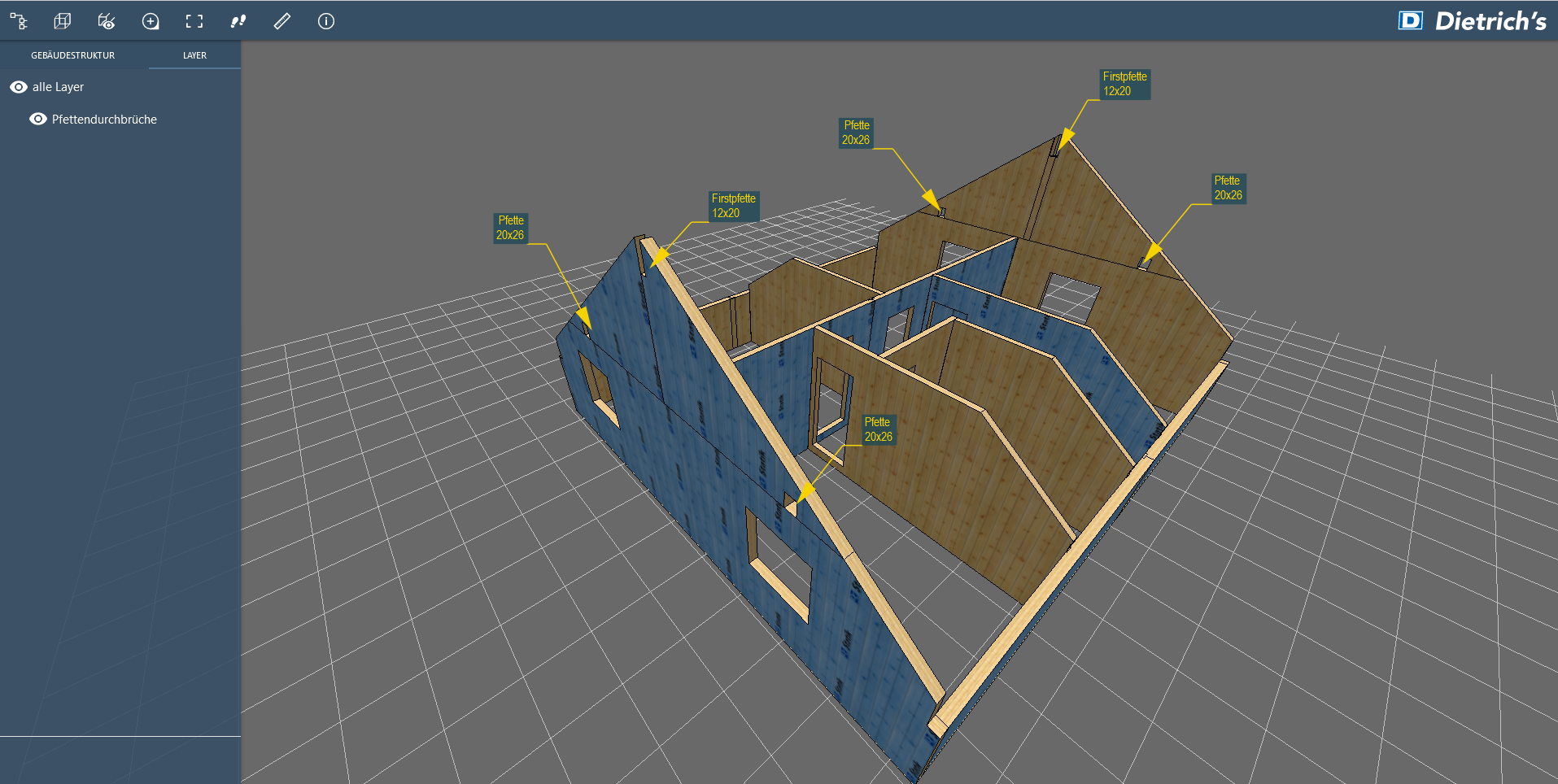
Transfer of 3D inscriptions to 3D web viewer
The 3D web viewer is increasingly establishing itself in the communication between the team and also with others involved in the project or the building owner. A logical addition is now the transfer of 3D inscriptions to the 3D web viewer. The important information is therefore visible directly at the place in question. The information is not overlooked and it is clear to what it refers.
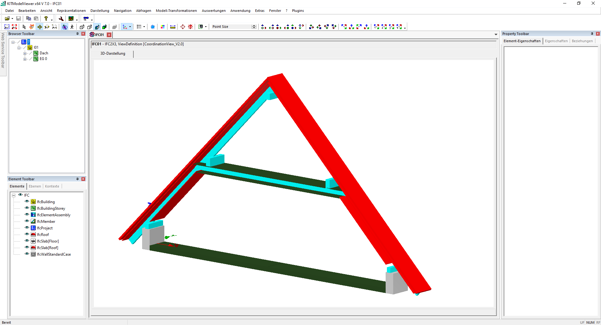
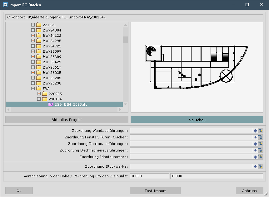
NEW! Speed of initial input, import
Collaboration as part of the BIM is gaining momentum, whilst the exchange of IFC files is now commonplace. IFC files are often very large and sometimes cluttered with “decorations” that have no meaning for the design or the BIM process. In order not to get bogged down in the work, a fast filtering process is important. For this purpose, it has been possible to reduce the time for first opening the IFC file by up to 90 %. The actual import can then be extensively optimised using the settings, particularly by excluding components (material, types such as furniture, ...) or building structures (storeys).
In terms of the IFC import itself, various optimisations have been able to be achieved. Among other things, further processes have been rearranged so that they can be calculated simultaneously on several computer cores (multithreading). Depending on the content of the IFC file, we have been able to reduce the time required here by up to 70 %.
DC-Calcs
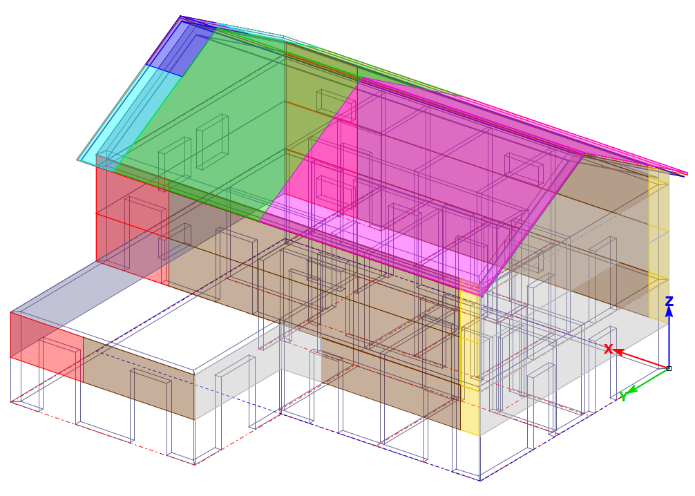
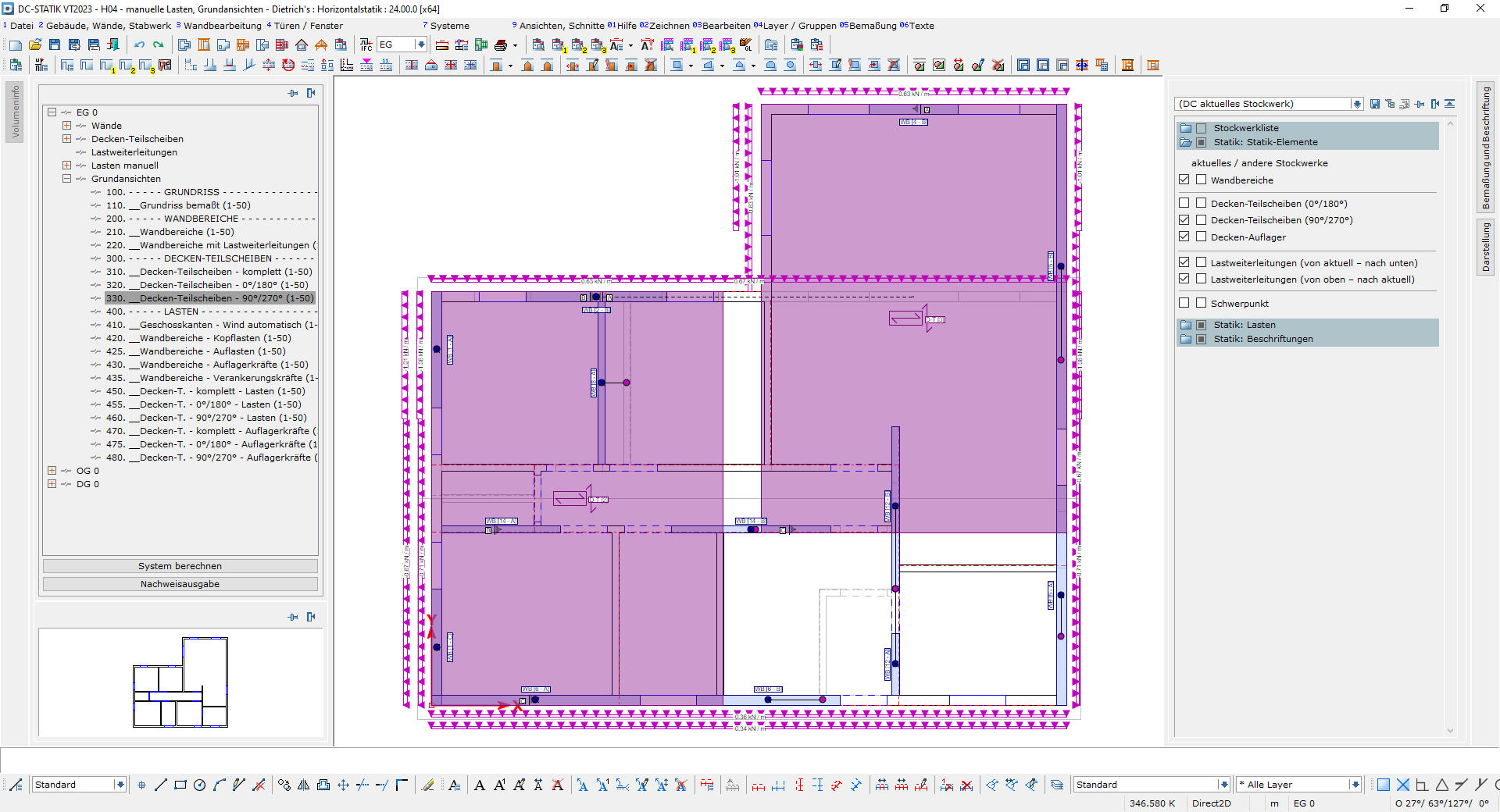
Building reinforcement becomes horizontal statics
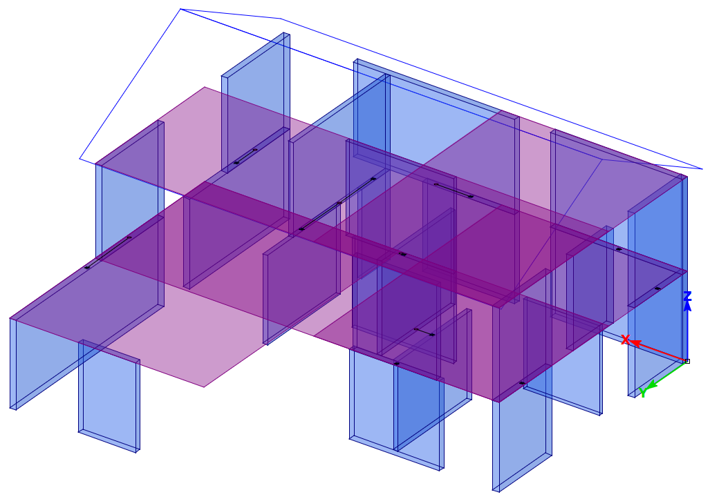
With our building reinforcement function, you can verify the stability of buildings directly in an integrated 3D model. After extensive customer feedback, we have completely revised the previous inputs and calculations in Version 24. This new concept now bears the name “Horizontal statics”. Besides the verifications for timber frame construction walls and balcony ceilings, another priority is on the complete transfer of horizontal loads through the entire building.
We have introduced purely static elements, such as wall areas and partial diaphragms, which enable a quick and easy definition of the load-bearing areas. In the static wall areas, set information about the timber frame construction allocation can be stored. This makes the inputs easier, as no wall construction is necessary. We have also enhanced the dimensioning of partial diaphragms. By resting these partial diaphragms on the wall areas underneath them, loads are introduced into the walls. Wall areas on top of each other are coupled with each other by load transmissions. The load flow through the entire building is generated by these links.
All inputs are made in the new horizontal statics model area. You can use the navigation dialogue to manage the new elements and the course of the loads through the building clearly and conveniently. All results are immediately available, meaning that adjustments and optimisations are visible straight away.
Steel profiles
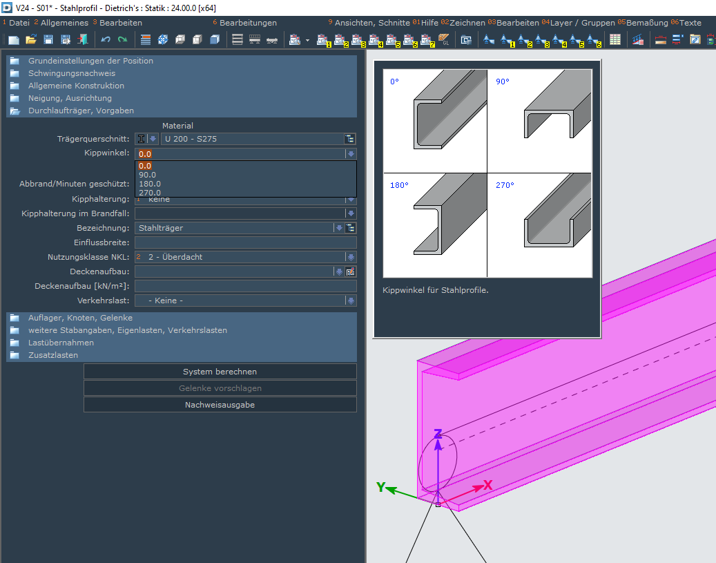
In timber construction, steel profiles help to bridge large spans with slim constructions and support high loads. We have updated the steel verifications in DC-Calcs and now calculate fully according to Eurocode 3 (EN 1993-1-1).
Besides the double-T profiles (HEA, HEB, IPE,...) and hollow profiles previously available for dimensioning, singly symmetrical profiles are now also used. We have added the verifications of the steel profiles for these cross-sections and integrated them for the calculation in the U and UPE profiles product selection.
Depending on the profiles’ direction of loading, it may be necessary to rotate the steel cross-section. The tilt angle has been added in the input of the steel profiles. The profiles can therefore be individually aligned.
The dimensioning of steel profiles is available to you in optional modules for continuous beams, struts and rafters.
IFC export and 3D DXF export
Do you create statics and want to forward the results to your project partners not only in paper format? The design model can now be easily exported with the IFC export and the 3D DXF export. In the extensive and flexible export settings, the files can be adapted to the requirements of the target software. You can thus transfer roof designs or complete framework designs, for example, to other CAD systems for further processing.
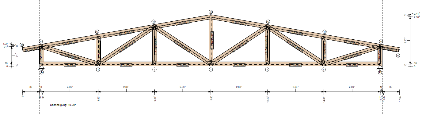
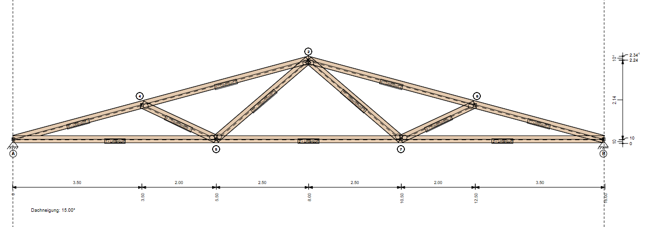
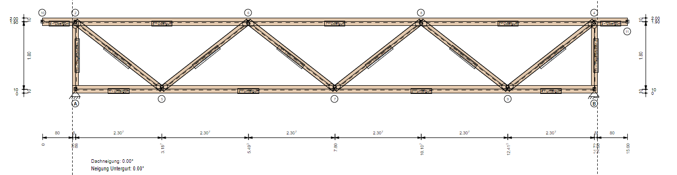
parametric frameworks for truss girder
Truss girders come in a wide variety of designs. It is all the more helpful if you use an adaptable system. Our parametric truss girders can be used to generate and verify framework designs at the press of a button. As the designs are in parametric format, they can be effortlessly adapted at any time.
With this year’s update you will get a parametric framework for parallel, pent and saddle roof trusses. The parametric allows the trusses to be easily adapted to the situation being verified. This enables framework designs with individual field lengths to be generated, for example. Single posts or struts can also be switched and aligned independent of each other.