
Dietrich’s Update V19
The most important updates at a glance
We are pleased to present the highlights of this release, giving you an overview of the most important additional features of Dietrich's 19 version. Dietrich's users receive a complete list of the features provided by the update. Here you will find useful tips that apply to the improvements, optimizations and modifications available on version 19 of Dietrich's.
- The main highlights : Working Planes as well as Sorting and Numbering
- New additional module : D-Ref Building
See for yourself which of the enhancements are important and valuable for making your daily work easier.
Have fun and success with the new features contained in your update!
Ergonomics
NEW! Working Planes - The Revolution in 3D-Construction
The introduction of the working planes allows you to work in a completely new way and revolutionizes free design. Working planes combine the advantages of 3D design with the advantages of inserting objects that directly on the selected working plane. The new working planes make 3D input much easier and extremely convenient.
- Special functions are called for entering structural elements and panels in the working planes in order to take advantage of the dimensional orientation.
- Support of the 2D plan elements lines, arcs and circles (auxiliary geometry) to determine geometric shapes and construction locations.
- Quick change of working planes; renaming, sorting or deleting via the familiar building navigation window.
- In the OpenGL workspace, you can restrict the display area to a defined section of the building around the workplane (clipbox). This allows you to reduce the display to what you want without switching off building elements. The familiar working grid is also available in the work planes.
- Graphical inputs of the 3D functions benefit from 2D working planes, since the coordinate system of the working plane has been aligned for the situation.
The new working plane function is part of the update for all DICAM versions and is available free of charge to our customers with a valid S&U* contract.
*(Service and Update)
Improved Transparent Rendering
For the transparent rendering in OpenGL (transparent objects) a new method with high rendering quality and the display of edges was implemented. The sequence of displaying the components in a logical order makes it possible to achieve a high-transparent rendering quality. You have access to all edges and points for placement and editing which would not have been as clear before in a hidden display. It makes it easier to stay in control of your 3D construction.
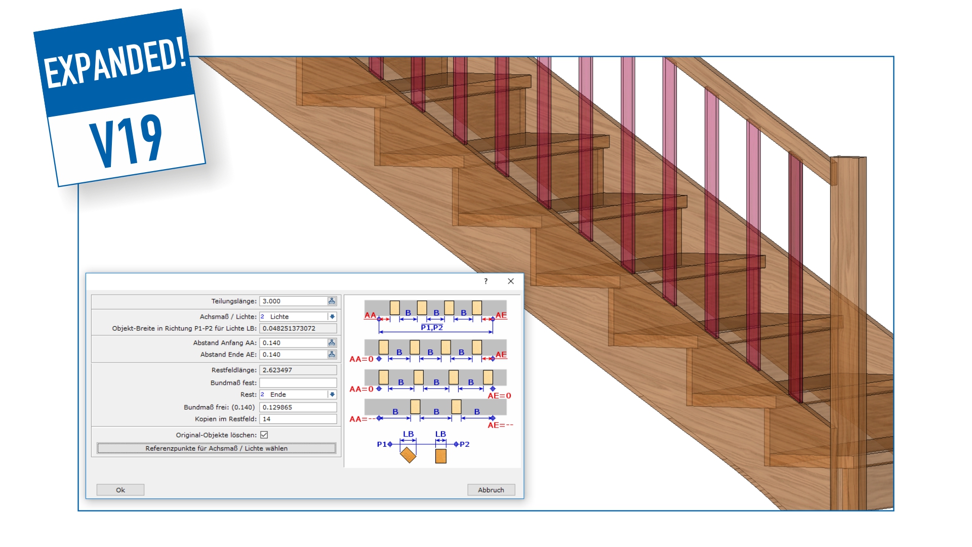
Copy and Distribution Function
You are confronted with rows and divisions of objects in your daily work. No matter whether lines for a grid division or spindles for balcony or staircase railing: something always has to be distributed at a certain distance along a section. The new copy function now offers you more control even for tricky tasks, for example when dividing with clear distances or working with free dimensions, both for 2D elements and for objects in 3D work environment. The immediate preview of the results during input of numbers of copies or distances, eliminates the need for tedious trial and error and allows you to reach your goal immediately.

Optimized Design in Plans
You can now shorten long parts in areas without modifications for display in plans. This allows larger scales to be used. Plans are now much clearer without losing important details.
Construction
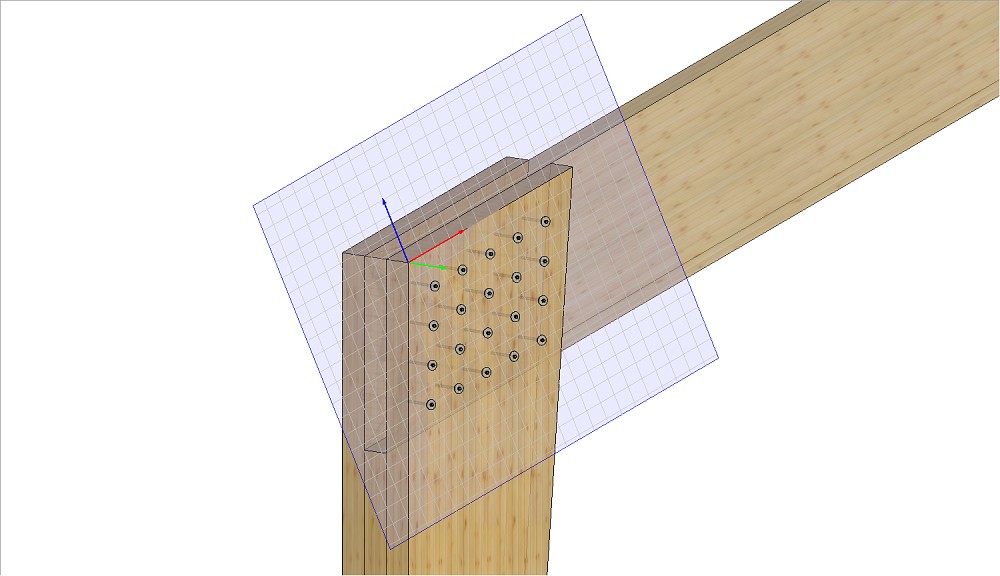
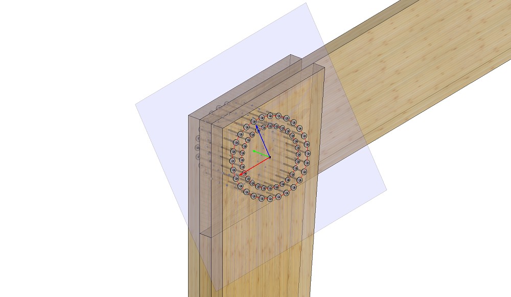
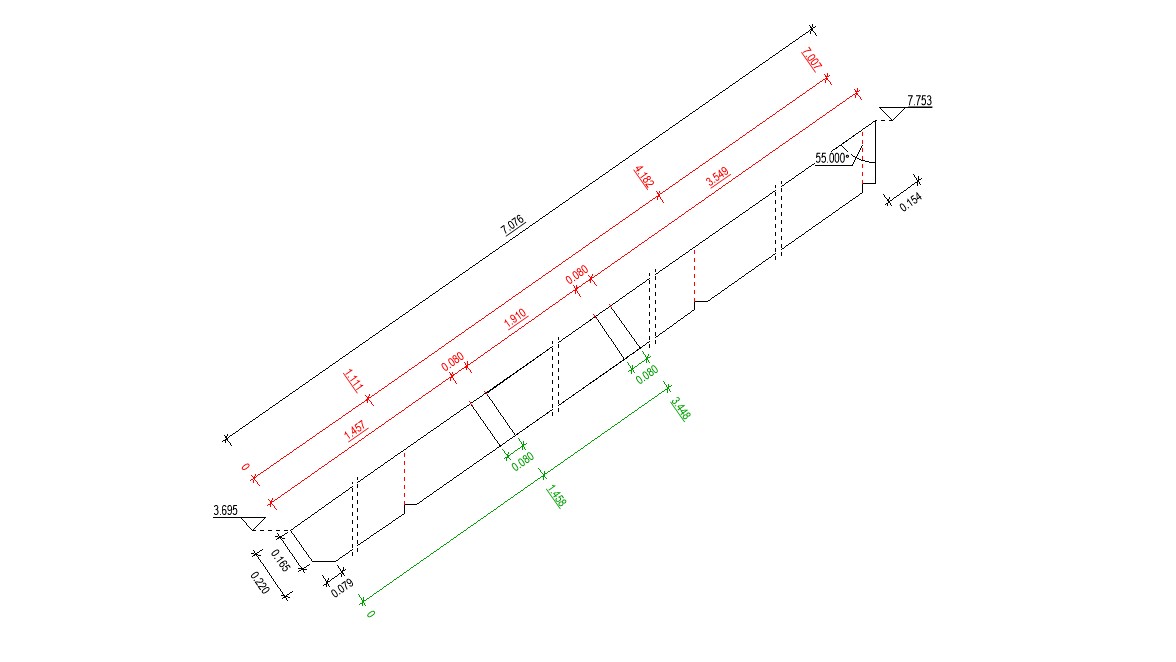
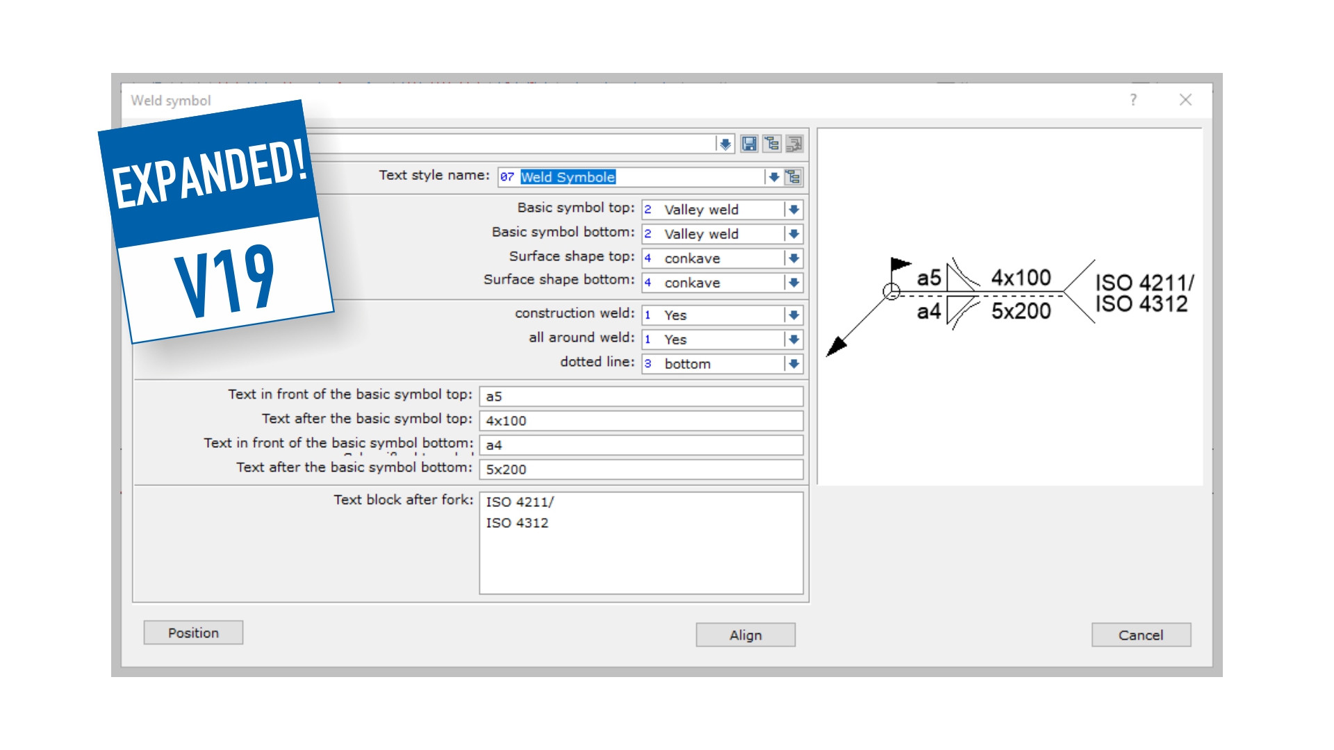
NEW! Module Extension: Welding Symbols
More and more custom steel constructions are used in modern wood construction, for example for load transfer in the case of large spans or for the connection of timbers. Most steel structures are joined by welding seams. The documentation of weld seams is carried out on the drawings, to work in accordance with the National Standards: DIN EN ISO 2553, for example. Weld symbols have a complex structure therefore the new dialog-guided input function "Weld Symbol" enables you to easily and effectively communicate and identify the welding seams with the correct symbols.
The new Logic Block called "Steel Construction" is now available, which benefits from this new addition.
After creating the settings for the local standards, those can be saved, managed, easily called up via the favorites and shared with other users.
BIM|Collaborative Work
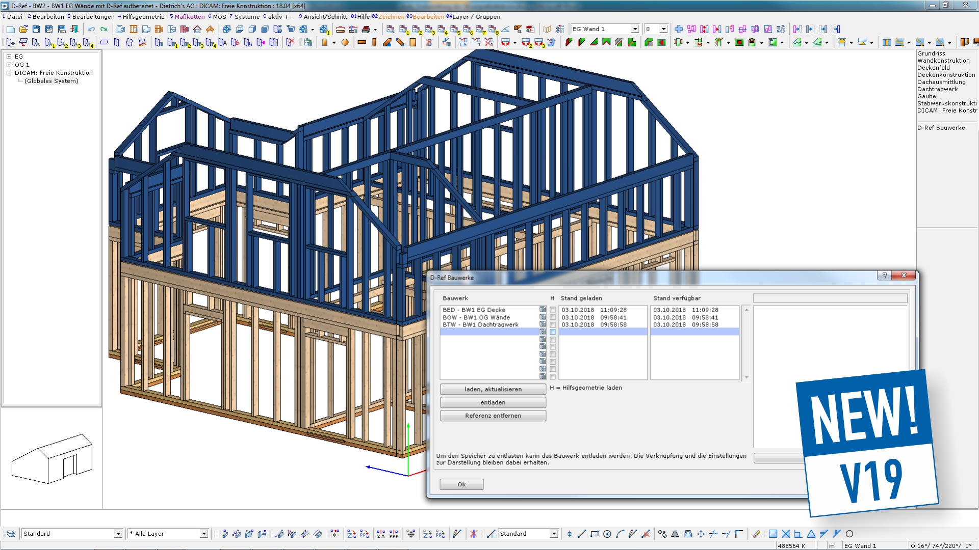
NEW! Module: D-Ref Building
The new module D-Ref Building offers you a completely new and innovative way for teamwork. With D-Ref you will be able to compare structures and easily find, track and resolve changes or collisions. D-Ref displays other structures from various projects. This new technology allows you to quickly compare different planning stages. Even the smallest changes are immediately visible.
You are able to divide a design into any number of building units. This is particularly advantageous when large buildings being constructed in phases or handled by different teams. In such cases, collision control is critical. This will show you immediately and distinguish clearly where components from the D-Ref Building collide with those of the current structure. That way it is guaranteed that all partial building units are perfectly come together during construction.
IFC Export
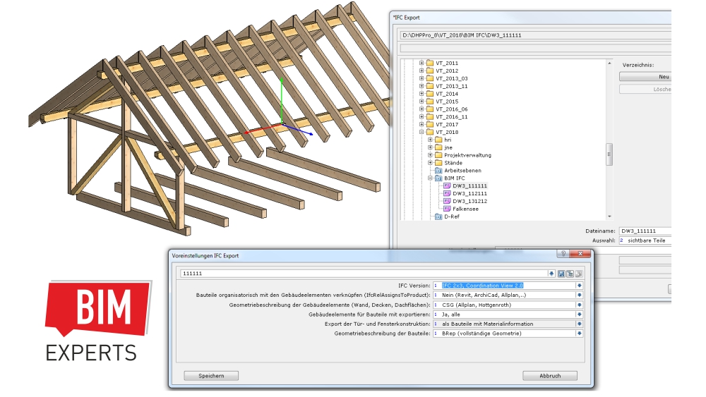
Specific export settings for various target systems
You want to exchange 3D Design files in an IFC file format to your partners, but their respective software does not support all IFC options. This will cause problems. With expanded IFC export settings, you are now able to take the requirements of the destination systems into account by making the appropriate settings:
- Scalable assignment and grouping of components: important for transfer to Allplan, Revit, etc.
- Geometry description in either CSG or BRep: important for transfer e.g. to Allplan
- Geometry description of components also via SweptSolid: important for transfer e.g. to Dlubal
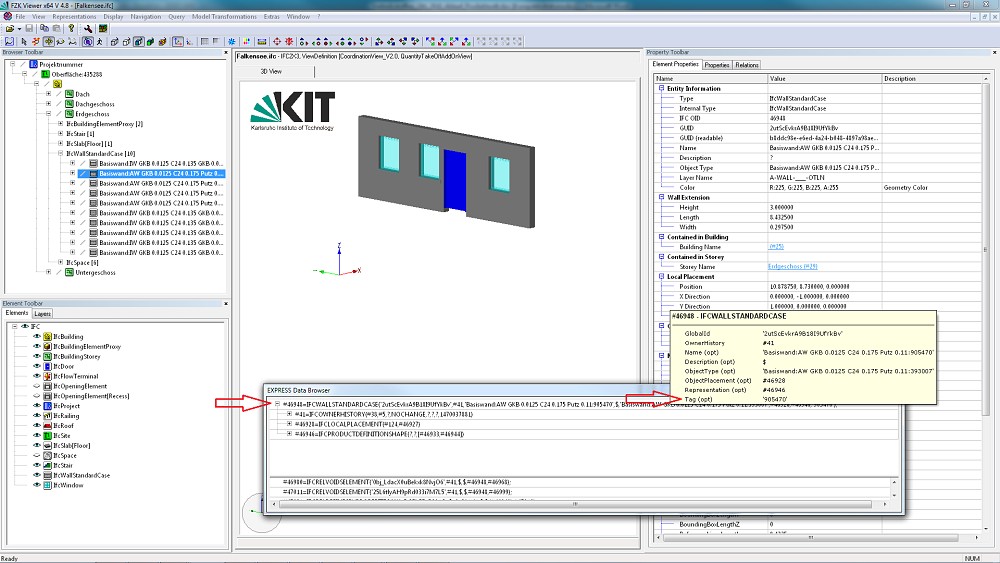
IFC-Import
On importing, wall numbers that come from the IFC file are automatically recognized and included. There is no need to correct the wall-numbers after import.
Organisation
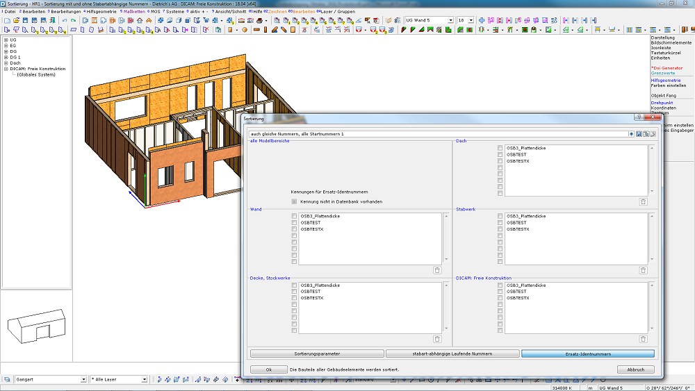
New Sorting and Numbering
Comprehensive organization from the design model through lists and plans, up to machine files is critical for a well-functioning production process - especially when collaborating with other project participants. The sorting number (object number within the building) of the components is of key importance. The proven sorting system has been expanded to include more control and flexibility to get the desired result. Fixed Sorting numbers for assembly sequence or correspondence with static position number, etc. can be assigned as well.
- Assigning of sorting number ranges to groups of components (e.g. purlins) in order to be able to recognize them by the sequence number: 100-150 for purlins, 200-400 for rafters, etc.is now possible.
- An additional option can be selected to prevents duplicate numbers in the entire building. That is critical for creating CNC processing file for some machines.
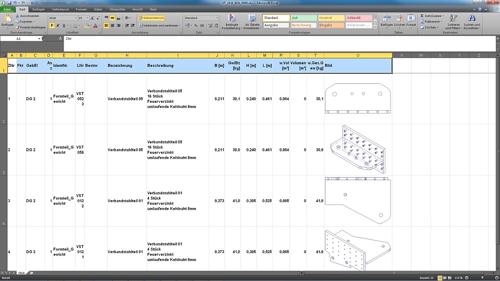
Component Assembly List
The use of subassemblies is becoming increasingly common in a building structure, especially for assembled steel components (gussets plates, custom steel connectors, etc.). The list of assemblies is now available for organization purposes, giving you a quick overview of the existing subassemblies, their assignment to building elements, total volume and weight. For easy recognition of the subassembly, an image can be stored for each line of the list. This enables, for example, better planning and faster verification list for of loading/unloading for the construction site.
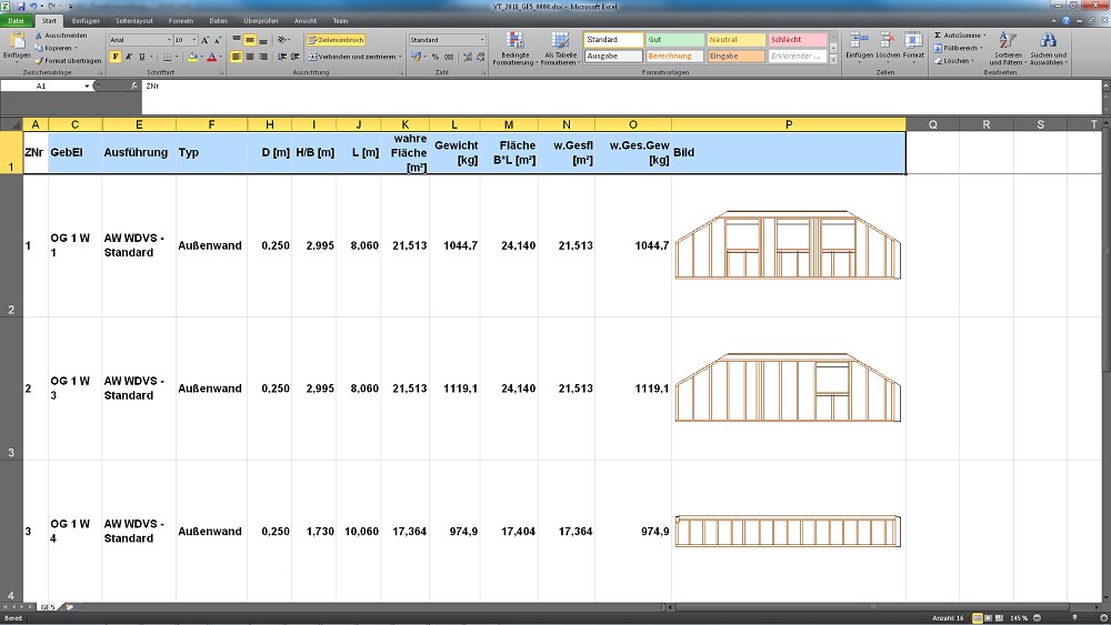
Building Element List
The various objects of a building are often organized into building elements (walls, ceilings, roof areas, frameworks). These can in addition be sup-divided into smaller production components. The building element list provides a quick overview of the existing building elements, their dimensions, visible areas, and weight. They are used, for example, for preparation and planning the stages of production, shipping/ loading and the assembly at the construction on site. Like the assembly list, the building element list also contains an illustration for fast and convenient identification of the elements and can of course be shared in different file formats or printed.